Before performing the diagnosis, check the following items which may cause problems in the A/C system.
1. Measure the battery voltage and specific gravity of the electrolyte.
Standard voltage:
12 V
Specific gravity:
1.260 or more
2. Check the condition of the fuses for A/C system power supply and other fuses.
3. Check the condition of harness and harness connector connections.
1. Turn the ignition switch to ON, and press the A/C switch.
2. Turn the temperature control dial to maximum hot position.
3. Set the outlet opening to the defroster position.
4. Turn the fan switch to MAX.
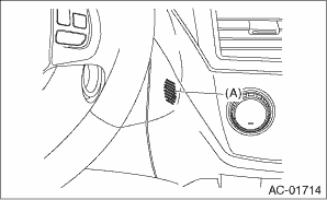
5. Put a thin strip of paper close to the front side of in-vehicle sensor suction port (A) at the instrument panel lower cover, and check whether the strip becomes drawn towards the port, indicating that air is being drawn in at the port.
NOTE:
Be careful not to let the paper get sucked into the port.
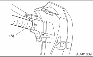
6. If the paper strip does not move at all, remove the instrument panel lower cover  , and check for improper connection of the aspirator hose (A), in-vehicle sensor and heater unit, and repair them if necessary.
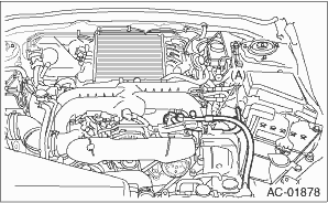
Check the connection for A/C line (A) and lower side high-pressure pipe.
1. Check the state of mode door linkage.
2. Check the state of air mix door linkage.
3. Check the state of FRESH/RECIRC door linkage.
Start the engine and warm up completely.
1. Inspection using switches
|
No. |
Point to check |
Switch operation |
Judgement standard |
|
1 |
Air flow control dial |
Turn the dial to the right. |
Outlet opening (mode) switches AUTO → VENT → BI-LEVEL → HEAT → DEF/HEAT → DEF each time turning the dial. |
|
2 |
Fan speed control dial |
Turn the dial to the right. |
Fan speed switches OFF → AUTO → 1st → 2nd → 3rd → 4th → 5th → 6th → 7th each time the dial is turned. |
|
3 |
FRESH/RECIRC switch |
Press the FRESH/RECIRC switch. |
Inlet opening switches RECIRC → FRESH → RECIRC each time pressing the switch. (LED illuminates at RECIRC) |
|
Set the air flow control dial and fan speed control dial to the AUTO position. |
The system switches to AUTO. | ||
|
4 |
A/C switch |
Turn the A/C switch to ON with the fan speed control dial set to except for OFF position. |
The LED lights and the compressor operates. |
|
Set the air flow control dial and fan speed control dial to the AUTO position. |
The system switches to AUTO. | ||
|
5 |
Auto function Operate in order starting from 1). |
1) Set the following dial and switch to AUTO. • Air flow control dial • Fan speed control dial • FRESH/RECIRC switch • A/C switch 2) Turn the temperature control dial completely to the left, and set to the maximum cool position. |
• Outlet air temperature: COOL • Fan speed: Max. • Outlet opening: VENT • Inlet opening: RECIRC • Compressor: AUTO |
|
3) Turn the temperature control dial to the right slowly up to the maximum hot position. |
• Outlet air temperature: COOL → HOT • Fan speed: AUTO • Outlet opening: AUTO • Inlet opening: AUTO • Compressor: AUTO | ||
|
4) Turn the temperature control dial fully to the right, to the maximum hot position. |
• Outlet air temperature: HOT • Fan speed: Max. • Outlet opening: HEAT • Inlet opening: FRESH • Compressor: AUTO | ||
|
6 |
Defroster interlock function |
Set the air flow control dial to the DEF or the DEF/HEAT position. |
• Outlet air temperature: AUTO • Fan speed: AUTO • Outlet opening: DEF or DEF/HEAT • Inlet opening: FRESH • Compressor: ON |
|
7 |
Rear defogger switch |
Press the rear defogger switch. |
LED illuminates. |
2. Inspection of compressor operation
|
No. |
Point to check |
Switch operation |
Judgement standard |
|
1 |
Compressor |
1) Turn the A/C switch to ON. 2) Set the FAN switch between LO and HI. |
Compressor: ON |
3. Inspection of illumination control
|
No. |
Point to check |
Switch operation |
Judgement standard |
|
1 |
Illumination |
Turn the lighting switch to ON. |
Illumination comes on. If the LED is lit, the LED will dim. |