|
Content |
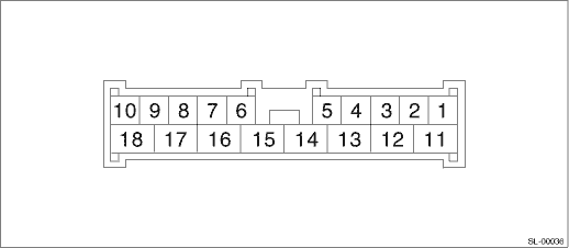
Terminal No. |
Measuring condition |
|
Key warning switch |
1 (INPUT) |
Battery voltage is present when inserting the key into ignition switch. |
|
Registration connector |
2 (INPUT) |
0 V is present when the registration connector is connected. |
|
Door switch |
3 (INPUT) |
0 V is present when the door is open. |
|
Power supply |
5 |
Battery voltage is constantly present. |
|
Ground |
6 |
0 V is constantly present. |
|
Empty |
7 |
— |
|
Door lock switch (UNLOCK) |
8 (INPUT) |
0 V is present when the door lock switch is turned to the UNLOCK side. |
|
Empty |
9 |
— |
|
Door lock switch (LOCK) |
10 (INPUT) |
0 V is present when the door lock switch is turned to the LOCK side. |
|
Room light/Ignition switch illumination |
11 (OUTPUT) |
• 0 V is present when the keyless transmitter OPEN button is pressed. • 0 V is present when the door is open. |
|
Turn signal light (LH) |
12 (OUTPUT) |
Battery voltage is present when pressing the keyless transmitter OPEN or LOCK button. |
|
Turn signal light (RH) |
13 (OUTPUT) |
Battery voltage is present when pressing the keyless transmitter OPEN or LOCK button. |
|
Ground |
14 |
0 V is constantly present. |
|
Power supply (Hazard light) |
15 |
Battery voltage is constantly present. |
|
Power supply |
16 |
Battery voltage is constantly present. |
|
Door and rear gate lock actuator (Model without double lock) or double lock unit (Model with double lock) |
17 (OUTPUT) |
Battery voltage is present when pressing the keyless transmitter OPEN button. |
|
Door and rear gate lock actuator (Model without double lock) or double lock unit (Model with double lock) |
18 (OUTPUT) |
Battery voltage is present when pressing the keyless transmitter LOCK button. |