1. Temporarily tighten the two bolts (bolts A) fixing pipe C and D in place.
NOTE:
Visually check that the hose between tank and pipe D is not bent or twisted.
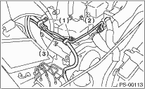
• Non-turbo model
|
(1) |
Bolt A |
|
(2) |
Pipe C |
|
(3) |
Pipe D |
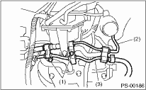
• Turbo model
|
(1) |
Bolt A |
|
(2) |
Pipe C |
|
(3) |
Pipe D |
(1) Connect pipe D to the reservoir tank.
(2) Install the pipe C to the oil pump using a new gasket.
Tightening torque:
40 N·m (4.1 kgf-m, 29.5 ft-lb)
(3) Tighten the two bolts (bolts A) fixing pipe C and D in place.
Tightening torque:
13 N·m (1.3 kgf-m, 9.4 ft-lb)
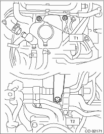
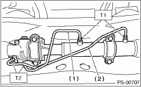
2. Install the coolant filler tank. (Turbo model)
Tightening torque:
T1: 16 N·m (1.6 kgf-m, 11.8 ft-lb)
T2: 13 N·m (1.3 kgf-m, 9.6 ft-lb)
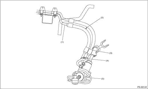
3. Temporarily connect the pipes C and D to the gearbox assembly.
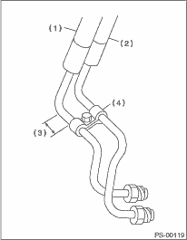
|
(1) |
Return hose |
|
(2) |
Pressure hose |
|
(3) |
Approx. 30 mm (1.18 in) |
|
(4) |
Clamp E |
4. Temporarily install clamp E on pipes C and D.
NOTE:
Make sure that the character “8” on each clamp is positioned on the same side, as shown in the figure.
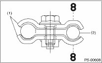
|
(1) |
Clamp E |
|
(2) |
Pipe C |
5. Tighten the clamp E.
Tightening torque:
7.4 N·m (0.75 kgf-m, 5.4 ft-lb)
6. Tighten the joint nut.
Tightening torque:
15 N·m (1.5 kgf-m, 11.1 ft-lb)
7. Connect the pipes A and B to the four pipe joints of gearbox. Connect the upper pipe B first, and lower pipe A.
Tightening torque:
T1: 24 N·m (2.4 kgf-m, 17.7 ft-lb)
T2: 20 N·m (2.0 kgf-m, 14.5 ft-lb)
|
(1) |
Pipe A |
|
(2) |
Pipe B |
8. Install the jack-up plate.
9. Install the air intake duct, the air cleaner upper cover and the air intake boot. 
10. Connect the battery ground cable to the battery.
11. Fill with the specified fluid.
CAUTION:
Never start the engine before filling with fluid; otherwise the vane pump may become seized.
12. Finally, check clearance between pipes or hoses as shown in the figure.
Pipe to cross member clearance:
10 mm (0.39 in) or more
|
(1) |
Clearance between blow-by hose and pipe: 3 — 5 mm (0.12 — 0.20 in) |
(3) |
Clearance between side frame and hose: 15 mm (0.59 in) or more |
(5) |
Steering gearbox |
|
(2) |
No interference is allowed between hoses. |
(4) |
Clearance between crossmember and pipe: 5 — 13 mm (0.20 — 0.51 in) |