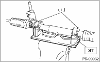
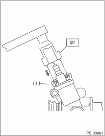
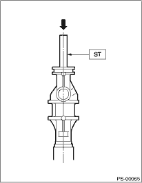
1. Secure the gearbox assembly removed from the vehicle in a vise using a ST.
| ST 926200000 | STAND |
CAUTION:
Secure the gearbox assembly in a vise using ST as shown. Do not affix the gearbox to the vice without this ST.
|
(1) |
Clamp |
2. Remove the tie-rod end and lock nut from gearbox assembly.
3. Move the clip of the boot using the pliers, and then slide the boot to the tie-rod end side.
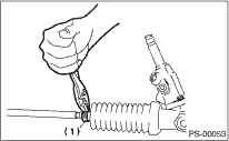
|
(1) |
Clip |
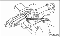
4. Using a flat tip screwdriver, remove the band from boot.
NOTE:
Replace the boot if there is damage, cracks or deterioration.
|
(1) |
Band |
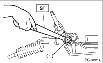
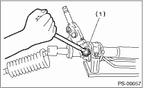
5. Using the ST, loosen the lock nut.
| ST 926230000 | SPANNER |
|
(1) |
Lock nut |
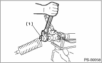
6. Tighten the adjusting screw until it can no longer be tightened.
|
(1) |
Adjusting screw |
7. Remove the tie-rod using a 32 mm (1.26 in) spanner or adjustable wrench.
|
(1) |
Tie-rod |
8. Loosen the adjusting screw, and remove the spring and sleeve.
9. Disconnect the pipes A and B from steering body and control valve housing.
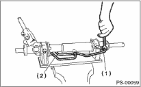
|
(1) |
Pipe A |
|
(2) |
Pipe B |
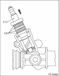
10. Clean any dirt adhered to the input shaft. Remove the dust cover, paying attention not to scratch the housing or input shaft and not to allow foreign matter to enter gear box interior.
CAUTION:
Wrap tape around the spline part of the input shaft to prevent the dust cover from being damaged.
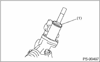
|
(1) |
Dust cover |
11. Align the ST pin with plug hole to install. Rotate the ST counterclockwise to remove plug.
| ST 34199AE090 | PLUG WRENCH |
|
(1) |
Plug |
12. Remove the valve assembly paying attention not to scratch the seal ring or valve housing inner surfaces.
|
(1) |
Valve ASSY |
|
(2) |
Seal ring |
13. Remove the holder using a 32 mm (1.26 in) spanner or adjustable wrench.
14. Attach the ST on the valve side of rack, and press out the outer side oil seal while taking care that the rack and the steering body inner surface do not come into contact with each other.
| ST 34199FE000 | INSTALLER & REMOVER |
NOTE:
Block the pipe connection of steering body to prevent fluid from flowing out.
|
(1) |
Rack piston |
|
(2) |
Outer side oil seal |
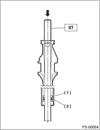
15. Insert the ST from the valve side and press the back-up ring and oil seal out.
| ST 927580000 | REMOVER |
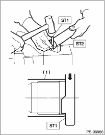
16. Using ST1 and ST2, repair the crimped portion of cylinder.
| ST1 34099FA080 | PUNCH |
| ST2 34099FA070 | BASE |
|
(1) |
Cylinder |
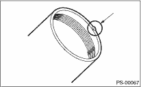
17. If the cylinder edge is deformed in a convex shape, repair using an oil stone.
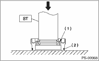
18. Remove the oil seal using ST and push out from the plug.
| ST 34199AE100 | OIL SEAL PLUG REMOVER |
NOTE:
Do not apply force on the plug edge surface.
|
(1) |
Oil seal |
|
(2) |
O-ring |
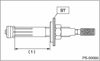
19. Set the ST at a size shown in the figure.
| ST 34199AE120 | GEARBOX OIL SEAL REMOVER |
|
(1) |
70 mm (2.76 in) |
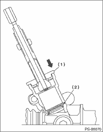
20. Set the stopper to gearbox, then insert the tip of the ST to the gearbox.
|
(1) |
Stopper |
|
(2) |
Oil seal |
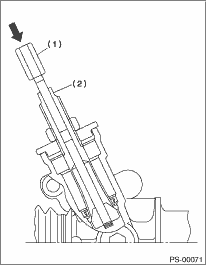
21. By fixing the 2-surface widths, press-in the rod while rotating it and catch the oil seal.
|
(1) |
Rod |
|
(2) |
2-surface widths |
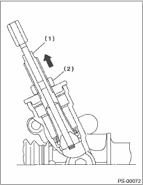
22. While fixing the 2-surface widths, pull out the oil seal by rotating nut.
CAUTION:
Take care not to scratch the gearbox inner surface.
|
(1) |
2-surface widths |
|
(2) |
Nut |