CONTROL SYSTEMS > AT Shift Lock Control System

INSPECTION

1. SHIFT LOCK OPERATION

STEPCHECKYESNO

1.CHECK SHIFT LOCK.

1) Turn the ignition switch to ON.

2) Move the select lever to “P” range.

While brake pedal is not depressed, can the select lever move from “P” range to other ranges?

Inspect “SELECT LEVER CANNOT BE SHIFT LOCKED”.

2.CHECK SHIFT LOCK.

While brake pedal is depressed, can select lever move from “P” range to other ranges?

Inspect “SELECT LEVER CANNOT BE SHIFTED”.

3.CHECK KEY INTERLOCK.

When the select lever is set to other than “P” range, can the ignition switch turned to the “LOCK” position?

Inspect “KEY INTERLOCK DOES NOT BE LOCK OR UNLOCK”.

4.CHECK KEY INTERLOCK.

When the select lever is in the “P” range, can the ignition switch be turned to the “LOCK” position?

AT shift lock control system is normal.

Inspect “KEY INTERLOCK DOES NOT BE LOCK OR UNLOCK”.

2. AT SHIFT LOCK CONTROL UNIT POWER AND GROUND CIRCUIT

WIRING DIAGRAM:

STEPCHECKYESNO

1.CHECK FUSE.

Remove the fuses No. 4, 6 and 18.

Are the fuses No. 4, 6 and 18 blown?

Replace the fuses No. 4, 6 and 18. If the replaced fuse No. 4, 6 or 18 blows out easily, repair the short circuit of harness between the fuse and AT shift lock control unit.

2.CHECK HARNESS CONNECTOR BETWEEN AT SHIFT LOCK CONTROL UNIT AND CHASSIS GROUND.

1) Turn the ignition switch to OFF.

2) Measure the resistance of the harness between the AT shift lock control unit and chassis ground.

Connector & terminal

LHD model

(B373) No. 10 — Chassis ground:

RHD model

(B376) No. 10 — Chassis ground:

Is the resistance less than 1 Ω?

Repair open circuit of harness between the AT shift lock control unit and chassis ground.

3.CHECK BATTERY POWER SUPPLY.

1) Turn the ignition switch to ON. (engine OFF)

2) Measure the voltage between AT shift lock control unit and chassis ground.

Connector & terminal

LHD model

(B373) No. 3 (+) — Chassis ground (−):

RHD model

(B376) No. 3 (+) — Chassis ground (−):

Is the voltage 9 V or more?

Repair open circuit of the harness between battery and AT shift lock control unit, and any poor contact in connectors.

4.CHECK IGNITION POWER SUPPLY CIRCUIT.

1) Turn the ignition switch to ACC.

2) Measure the voltage between AT shift lock control unit and chassis ground.

Connector & terminal

LHD model

(B373) No. 7 (+) — Chassis ground (−):

RHD model

(B376) No. 7 (+) — Chassis ground (−):

Is the voltage 9 V or more?

Repair open circuit of the harness between battery and AT shift lock control unit, and any poor contact in connectors.

5.CHECK IGNITION POWER SUPPLY CIRCUIT.

1) Turn the ignition switch to ON. (engine OFF)

2) Measure the voltage between the AT shift lock control module and chassis ground.

Connector & terminal

LHD model

(B373) No. 1 (+) — Chassis ground (−):

RHD model

(B376) No. 1 (+) — Chassis ground (−):

Is the voltage 9 V or more?

Repair open circuit of the harness between battery and AT shift lock control unit, and any poor contact in connectors.

6.CHECK POOR CONTACT.

Is there poor contact in the connector?

Repair the poor contact.

Replace the AT shift lock control module.

3. SELECT LEVER CANNOT BE SHIFTED

WIRING DIAGRAM:

STEPCHECKYESNO

1.CHECK STOP LIGHT SWITCH.

Depress the brake pedal.

Does the stop light illuminate?

Check the stop light system.

2.CHECK HARNESS BETWEEN STOP LIGHT SWITCH AND AT SHIFT LOCK CONTROL MODULE.

1) Turn the ignition switch to OFF.

2) Disconnect AT shiftlock control unit and stop light switch connectors.

3) Measure the resistance of the harness between the stop light switch and AT shiftlock control unit.

Connector & terminal

Model without cruise control system

LHD model

(B64) No. 2 — (B373) No. 4

RHD model

(B64) No. 2 — (B376) No. 4

Model with cruise control system

LHD model

(B65) No. 3 — (B373) No. 4

RHD model

(B65) No. 3 — (B376) No. 4

Is the resistance 1 MΩ or more?

Repair open circuit of harness between the AT shift lock control unit and the stop light switch.

3.CHECK HARNESS BETWEEN STOP LIGHT SWITCH AND AT SHIFT LOCK CONTROL MODULE.

Measure the resistance of harness between stop light switch and chassis ground.

Connector & terminal

Model without cruise control system

(B64) No. 2 — Chassis ground:

Model with cruise control system

(B65) No. 3 — Chassis ground:

Is the resistance less than 1 Ω?

Repair short circuit of harness between the AT shift lock control unit and the stop light switch.

4.CHECK HARNESS BETWEEN AT SHIFT LOCK CONTROL MODULE AND SHIFT LOCK SOLENOID.

1) Disconnect the connector of shift lock solenoid.

2) Measure the resistance of the harness between the AT shift lock control module and shift lock solenoid.

Connector & terminal

LHD model

(B117) No. 4 — (B373) No. 6

RHD model

(B117) No. 4 — (B376) No. 6

Is the resistance 1 MΩ or more?

Repair open circuit of the harness between AT shift lock control module and shift lock solenoid.

5.CHECK HARNESS BETWEEN AT SHIFT LOCK CONTROL MODULE AND SHIFT LOCK SOLENOID.

Measure the resistance of harness between shift lock solenoid and chassis ground.

Connector & terminal

(B117) No. 4 — Chassis ground:

Is the resistance less than 1 Ω?

Repair short circuit of the harness between AT shift lock control module and shift lock solenoid.

6.CHECK HARNESS BETWEEN SHIFT LOCK SOLENOID AND CHASSIS GROUND.

Measure the resistance of harness between shift lock solenoid and chassis ground.

Connector & terminal

(B117) No. 5 — Chassis ground:

Is the resistance 1 MΩ or more?

Repair open circuit of harness between shift lock solenoid and chassis ground.

7.CHECK SHIFT LOCK SOLENOID.

Measure the resistance of the shift lock solenoid connector terminals.

Terminal

No. 4 — No. 5:

Is the resistance between 7 — 18 Ω?

Replace the shift lock solenoid.

8.CHECK SHIFT LOCK SOLENOID.

Connect the battery to connector terminal of shift lock solenoid, and operate the solenoid.

Terminal

No. 4 (+) — No. 5 (−):

Is the shift lock solenoid operating properly?

Replace the shift lock solenoid.

9.CHECK POOR CONTACT.

Is there poor contact in the connector?

Repair the poor contact.

Replace the AT shift lock control module.

4. SELECT LEVER CANNOT BE SHIFT LOCKED

WIRING DIAGRAM:

STEPCHECKYESNO

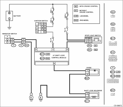
1.CHECK INHIBITOR SWITCH.

1) Turn the ignition switch to ON. (engine OFF)

2) Move the select lever from “P” to “1” range.

Combination meter indicator light and select lever “P”, “R”, “N”, “3”, “2” and “1” are correctly matched?

Adjust inhibitor switch and select cable.

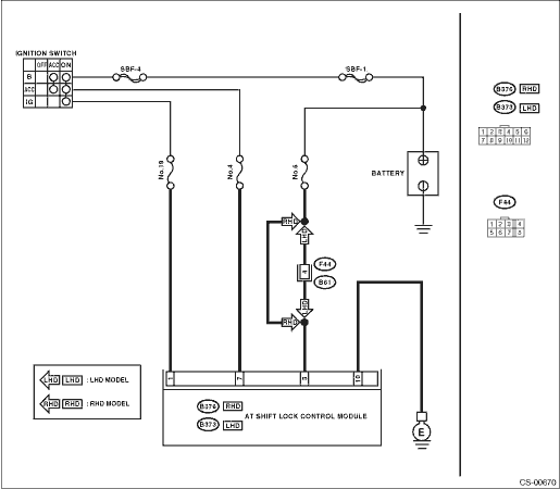
2.CHECK IGNITION POWER SUPPLY CIRCUIT.

1) Turn the ignition switch to ON. (engine OFF)

2) Measure the voltage between the AT shift lock control module and chassis ground.

Connector & terminal

LHD model

(B373) No. 1 (+) — Chassis ground (−):

RHD model

(B376) No. 1 (+) — Chassis ground (−):

Is the voltage 9 V or more?

Repair open circuit of the harness between battery and AT shift lock control unit, and any poor contact in connectors.

3.CHECK HARNESS BETWEEN INHIBITOR SWITCH AND AT SHIFT LOCK CONTROL MODULE.

1) Turn the ignition switch to OFF.

2) Disconnect AT shift lock control unit and transmission harness connectors.

3) Measure the resistance of the harness between the AT shift lock control unit and chassis ground.

Connector & terminal

LHD model

(B373) No. 2 — Chassis ground:

RHD model

(B376) No. 2 — Chassis ground:

Is the resistance less than 1 Ω?

Repair short circuit of the harness between the AT shift lock control unit and transmission connector.

4.CHECK HARNESS BETWEEN INHIBITOR SWITCH AND AT SHIFT LOCK CONTROL MODULE.

Measure the resistance of the harness between the AT shift lock control unit and inhibitor switch.

Connector & terminal

LHD model

(B12) No. 3 — (B373) No. 2:

RHD model

(B12) No. 3 — (B376) No. 2:

Is the resistance 1 MΩ or more?

Repair open circuit of harness between the AT shift lock control unit and the transmission connector.

5.CHECK HARNESS BETWEEN INHIBITOR SWITCH AND CHASSIS GROUND.

Measure the resistance of the harness between the AT shift lock control unit and chassis ground.

Connector & terminal

(B12) No. 4 — Chassis ground:

Is the resistance less than 1 Ω?

Repair open circuit of harness between the AT shift lock control unit and chassis ground.

6.CHECK INHIBITOR SWITCH.

1) Move the select lever to “P” range.

2) Measure the resistance between transmission harness connector terminals.

Connector & terminal

(T3) No. 3 — No. 4:

Is the resistance 1 MΩ or more?

Repair or replace inhibitor switch.

7.CHECK OUTPUT SIGNAL FOR AT SHIFT LOCK CONTROL MODULE.

1) Connect all connectors.

2) Turn the ignition switch to ON.

3) Measure the voltage between the AT shift lock control module and chassis ground.

Connector & terminal

LHD model

(B373) No. 2 (+) — Chassis ground (−):

RHD model

(B376) No. 2 (+) — Chassis ground (−):

Is the voltage 9 — 16 V?

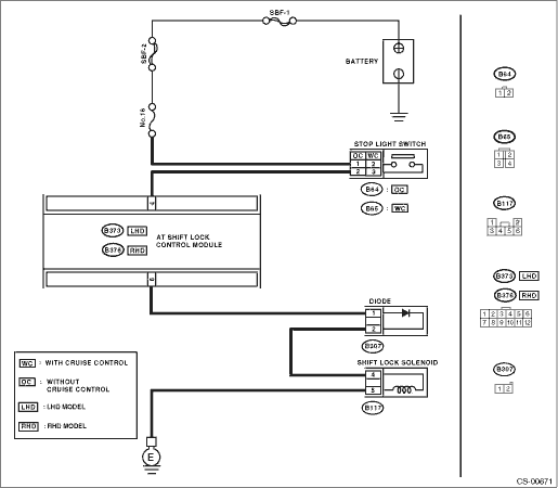
8.CHECK STOP LIGHT SWITCH.

Depress the brake pedal.

Does the stop light illuminate?

Check the stop light system.

9.CHECK HARNESS BETWEEN STOP LIGHT SWITCH AND AT SHIFT LOCK CONTROL MODULE.

1) Depress the brake pedal.

2) Measure the voltage between the AT shift lock control module and chassis ground.

Connector & terminal

LHD model

(B373) No. 4 (+) — Chassis ground (−):

RHD model

(B376) No. 4 (+) — Chassis ground (−):

Is the voltage 9 V or more?

Repair open circuit of harness between the AT shift lock control module and the stop light switch.

10.CHECK HARNESS BETWEEN AT SHIFT LOCK CONTROL MODULE AND SHIFT LOCK SOLENOID.

1) Turn the ignition switch to OFF.

2) Disconnect the shift lock solenoid and AT shiftlock control module connectors.

3) Measure the resistance of the harness between the AT shift lock control module and shift lock solenoid.

Connector & terminal

LHD model

(B373) No. 6 — (B117) No. 4:

RHD model

(B376) No. 6 — (B117) No. 4:

Is the resistance 1 MΩ or more?

Repair open circuit of the harness between AT shift lock control module and shift lock solenoid.

11.CHECK HARNESS BETWEEN AT SHIFT LOCK CONTROL MODULE AND SHIFT LOCK SOLENOID.

Measure the resistance of harness between shift lock solenoid and chassis ground.

Connector & terminal

LHD model

(B373) No. 6 — Chassis ground:

RHD model

(B376) No. 6 — Chassis ground:

Is the resistance less than 10 Ω?

Repair short circuit of the harness between AT shift lock control module and shift lock solenoid.

12.CHECK HARNESS BETWEEN SHIFT LOCK SOLENOID AND CHASSIS GROUND.

Measure the resistance of harness between shift lock solenoid and chassis ground.

Connector & terminal

(B117) No. 5 — Chassis ground:

Is the resistance less than 1 Ω?

Repair open circuit of harness between shift lock solenoid and chassis ground.

13.CHECK SHIFT LOCK SOLENOID.

Measure the resistance of the shift lock solenoid connector terminals.

Terminal

No. 4 — No. 5:

Is the resistance between 7 — 18 Ω?

Replace the shift lock solenoid.

14.CHECK SHIFT LOCK SOLENOID.

Connect the battery to connector terminal of shift lock solenoid, and operate the solenoid.

Terminal

No. 4 (+) — No. 5 (−):

Is the shift lock solenoid operating properly?

Replace the shift lock solenoid.

15.CHECK OUTPUT SIGNAL FOR AT SHIFT LOCK CONTROL MODULE.

1) Turn the ignition switch to ON. (engine OFF)

2) Measure the voltage between the AT shift lock control module and chassis ground.

Connector & terminal

LHD model

(B373) No. 6 (+) — Chassis ground (−):

RHD model

(B376) No. 6 (+) — Chassis ground (−):

Is the voltage 8.5 V or more?

Replace the AT shift lock control module.

16.CHECK POOR CONTACT.

Is there poor contact in the connector?

Repair the poor contact.

Replace the AT shift lock control module.

5. KEY INTERLOCK DOES NOT LOCK OR RELEASE

WIRING DIAGRAM:

STEPCHECKYESNO

1.CHECK HARNESS BETWEEN BATTERY AND KEY WARNING SWITCH.

1) Disconnect the connector of key warning switch.

2) Measure the voltage of harness between key warning switch and chassis ground.

Connector & terminal

(B74) No. 1 (+) — Chassis ground (−):

Is the voltage 9 — 16 V?

Repair the open or short circuit of harness between battery and key warning switch.

2.CHECK KEY WARNING SWITCH.

Measure the resistance between connector terminals of key warning switch.

Terminal

No. 1 — No. 2:

Is the resistance 1 MΩ or more?

Replace the key warning switch.

3.CHECK KEY WARNING SWITCH.

1) Remove the key.

2) Measure the resistance between connector terminals of key warning switch.

Terminal

No. 1 — No. 2:

Is the resistance 1 MΩ or more?

Replace the key warning switch.

4.CHECK HARNESS BETWEEN AT SHIFT LOCK CONTROL MODULE AND KEY WARNING SWITCH.

1) Disconnect the AT shift lock control module connector.

2) Measure the voltage between the AT shift lock control module and chassis ground.

Connector & terminal

LHD model

(B373) No. 8 (+) — Chassis ground (−):

RHD model

(B376) No. 8 (+) — Chassis ground (−):

Is the voltage 9 V or more?

Repair open circuit of harness between the AT shift lock control module and the key warning switch.

5.CHECK HARNESS BETWEEN AT SHIFT LOCK CONTROL MODULE AND KEY LOCK SOLENOID.

1) Disconnect the connector key lock solenoid.

2) Measure the resistance of the harness between the AT shift lock control module and key lock solenoid.

Connector & terminal

(B74) No. 5 — (B373) No. 9:

Is the resistance 1 MΩ or more?

Repair open circuit of the harness between AT shift lock control module and key lock solenoid.

6.CHECK HARNESS BETWEEN AT SHIFT LOCK CONTROL MODULE AND KEY LOCK SOLENOID.

Measure the resistance of the harness between the AT shift lock control unit and chassis ground.

Connector & terminal

LHD model

(B373) No. 9 — Chassis ground:

RHD model

(B376) No. 9 — Chassis ground:

Is the resistance 1 Ω or more?

Repair short circuit of the harness between AT shift lock control module and key lock solenoid.

7.CHECK HARNESS BETWEEN KEY LOCK SOLENOID AND CHASSIS GROUND.

Measure the resistance of harness between key lock solenoid and chassis ground.

Connector & terminal

(B74) No. 6 — Chassis ground:

Is the resistance less than 10 Ω?

Repair open circuit of harness between key lock solenoid and chassis ground.

8.CHECK KEY LOCK SOLENOID.

Measure the resistance of key lock solenoid connector terminals.

Terminal

No. 5 — No. 6:

Is the resistance between 4 — 8 Ω?

Replace the key lock solenoid.

9.CHECK HARNESS BETWEEN “P” RANGE SWITCH AND CHASSIS GROUND.

Measure the resistance of harness between “P” range switch and chassis ground.

Connector & terminal

(B117) No. 2 — Chassis ground:

Is the resistance less than 1 Ω?

Repair short circuit of harness between the P range switch and the AT shift lock control module.

10.CHECK HARNESS BETWEEN AT SHIFT LOCK CONTROL MODULE AND “P” RANGE SWITCH.

1) Disconnect the connector of the “P” range switch.

2) Measure the resistance of the harness between the AT shift lock control module and P range switch.

Connector & terminal

LHD model

(B117) No. 2 — (B373) No. 5:

RHD model

(B117) No. 2 — (B376) No. 5:

Is the resistance 1 MΩ or more?

Repair the open circuit of the harness between the AT shift lock control module and P range switch.

11.CHECK HARNESS BETWEEN “P” RANGE SWITCH AND CHASSIS GROUND.

Measure the resistance of harness between “P” range switch and chassis ground.

Connector & terminal

(B117) No. 6 — Chassis ground:

Is the resistance 1 MΩ or more?

Repair the open circuit of harness between “P” range switch and chassis ground.

12.CHECK “P” RANGE SWITCH.

1) Move the select lever to “P” range.

2) Measure the resistance between “P” range switch connector terminals.

Terminal

No. 2 — No. 6:

Is the resistance less than 1 Ω?

Replace the “P” range switch.

13.CHECK “P” RANGE SWITCH.

1) Set the select lever to other than “P” range.

2) Measure the resistance between “P” range switch connector terminals.

Terminal

No. 2 — No. 6:

Is the resistance 1 MΩ or more?

Replace the “P” range switch.

14.CHECK OUTPUT SIGNAL FOR AT SHIFT LOCK CONTROL MODULE.

1) Disconnect all connectors.

2) Turn the ignition switch to ON. (engine OFF)

3) Move the select lever to “P” range.

4) Depress the brake pedal.

5) Measure the voltage between the AT shift lock control module connector and chassis ground.

Connector & terminal

LHD model

(B373) No. 9 (+) — Chassis ground (−):

RHD model

(B376) No. 9 (+) — Chassis ground (−):

Is the voltage 7.5 — 16 V?

Replace the AT shift lock control module.

15.CHECK POOR CONTACT.

Is there poor contact in the connector?

Repair the poor contact.

Replace the AT shift lock control module.