|
Item |
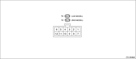
To connector No. |
Terminal No. |
Input/Output signal |
|
Measured value and measuring condition | |||
|
Battery power supply |
LHD model B373 RHD Model B376 |
3 |
9 — 16 V |
|
Ignition power supply |
1 |
10 — 15 V when ignition switch is at ON or START. | |
|
ACC power supply |
7 |
10 — 15 V when ignition switch is at ACC or ON. | |
|
Inhibitor switch (“P” range) |
2 |
0 V when select lever is in “P” range. 9 — 16 V when select lever is in other positions than “P” range. | |
|
Stop light switch |
4 |
9 — 16 V when stop light switch is ON. 0 V when stop light switch is OFF. | |
|
“P” range switch |
5 |
0 V when select lever is in “P” range. 9 — 16 V when select lever is in other positions than “P” range. | |
|
Shift lock solenoid signal |
6 |
8.5 — 16 V when shift lock is released. 0 V when shift lock is operating. | |
|
Key warning switch signal |
8 |
9 — 16 V when key is inserted. 0 V when key is removed. | |
|
Key lock solenoid signal |
9 |
Pulse is output when switching key lock between locked and unlocked. 0 V at other conditions than above. | |
|
Ground |
10, 11 |
— |