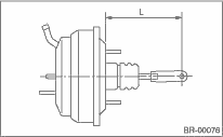
1. Check and adjust the operating rod of the brake booster.
Specification L:
LHD model: 144.6 mm (5.69 in)
RHD model: 173.2 mm (6.82 in)
If it is out of specification, adjust it with the brake booster operating rod.
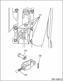
2. Mount the brake booster in position.
3. Connect the operating rod to brake pedal with clevis pin and snap pin.
|
(1) |
Nut |
|
(2) |
Clevis pin |
|
(3) |
Snap pin |
|
(4) |
Operating rod |
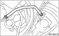
4. Connect the vacuum hose to brake booster.
5. Mount the master cylinder onto the brake booster.
6. Connect the brake pipes to the master cylinder.
Tightening torque:
Model with ABS:
15 N·m (1.5 kgf-m, 11.1 ft-lb)
Model with VDC:
19 N·m (1.9 kgf-m, 13.6 ft-lb)
7. Connect the connector of the brake fluid level gauge.
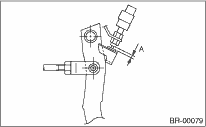
8. Measure the clearance between the threaded end of the stop light switch and the stopper.
If it is not within the specification, adjust it by adjusting the position of the stop light switch. 
CAUTION:
Do not rotate the stop light switch.
Stop light switch clearance A:
0.3 mm (0.012 in)
9. Apply grease to the operating rod connecting pin to prevent it from wear.
10. Bleed air from brake system.
Tightening torque (air bleeder screw):
8 N·m (0.8 kgf-m, 5.8 ft-lb)
11. Perform a road test to make sure the brakes do not drag.