1. Check the connection and fixture of the connector.
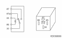
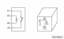
2. Inspect the valve relay and motor relay for broken wires or short circuits.
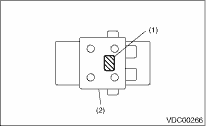
3. Inspect the identification of the VDCH/U.
Refer to “SPECIFICATION” for the identification mark. 
|
(1) |
Identification mark |
|
(2) |
VDCH/U |
|
Condition |
Terminal No. |
Standard |
||
|
Valve relay |
When not applying voltage |
85 — 86 |
103±10 Ω |
|
|
30 — 87a |
Less than 0.5 Ω | |||
|
30 — 87 |
1 MΩ or more | |||
|
When voltage (DC 12 V) is applied between terminal numbers 85 and 86. |
30 — 87a |
1 MΩ or more | ||
|
30 — 87 |
Less than 0.5 Ω | |||
|
Motor relay |
When not applying voltage |
85 — 86 |
80±10 Ω |
|
|
30 — 87 |
1 MΩ or more | |||
|
When voltage (DC 12 V) is applied between terminal numbers 85 and 86. |
30 — 87 |
Less than 0.5 Ω |
1. CHECKING THE VDCH/U ABS OPERATION BY PRESSURE GAUGE
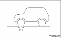
1. Lift up the vehicle, and remove the wheels.
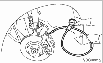
2. Disconnect the air bleeder screws from FL and FR caliper bodies.
3. Connect two pressure gauges to FL and FR caliper bodies.
CAUTION:
• Use a pressure gauge used exclusively for brake fluid measurement.
• Do not use a pressure gauge used previously for measurement of transmission oil pressure, as the piston seal may expand and deform.
NOTE:
Wrap sealing tape around the pressure gauge.
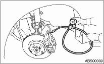
4. Bleed air from the pressure gauge.
5. Perform ABS sequence control.
6. When the VDCH/U begins to work, first the FL side performs decompression, hold and compression, and then the FR side performs decompression, hold and compression.
7. Read values indicated on the pressure gauge and check whether the fluctuation of the values between decompression and compression meets the standard values. Also check whether any irregular tightness of the brake pedal can be felt.
|
Front wheel |
Rear wheel | |
|
Initial value |
3,500 kPa (36 kgf/cm2, 512 psi) |
3,500 kPa (36 kgf/cm2, 512 psi) |
|
When depressurized |
500 kPa (5 kgf/cm2, 71 psi) or less |
500 kPa (5 kgf/cm2, 71 psi) or less |
|
When pressurized |
3,500 kPa (36 kgf/cm2, 512 psi) or less |
3,500 kPa (36 kgf/cm2, 512 psi) or more |
8. Disconnect the pressure gauges from FL and FR caliper bodies.
9. Install the air bleeder screws of FL and FR caliper bodies.
10. Remove the air bleeder screws from RL and RR caliper bodies.
11. Connect two pressure gauges to RL and RR caliper bodies.
12. Bleed air from RL and RR caliper bodies, and pressure gauge.
13. Perform ABS sequence control.
14. When the VDCH/U begins to work, first the RR side performs decompression, hold and compression, and then the RL side performs decompression, hold and compression.
15. Read the values indicated on the pressure gauges and check if it is within specification.
16. After checking, remove the pressure gauges from the caliper bodies.
17. Install the air bleeder screws of RL and RR caliper bodies.
18. Bleed air from the brake line.
2. CHECKING VDCH/U ABS OPERATION WITH THE BRAKE TESTER
1. Prepare for ABS sequence control.
2. Set the front wheels or rear wheels on the brake tester and set the select lever position to the “N” range.
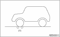
|
(1) |
Brake tester |
3. Operate the brake tester.
4. Perform ABS sequence control.
5. When the VDCH/U begins to work, check the following working sequence.
(1) The FL wheel performs decompression, hold and compression in sequence, and subsequently the FR wheel repeats the cycle.
(2) The RR wheel performs decompression, hold and compression in sequence, and subsequently the RL wheel repeats the cycle.
6. Read values indicated on the brake tester and check if the fluctuation of the values between decompression and compression meets specification.
|
Front wheel |
Rear wheel | |
|
Initial value |
1,000 N (102 kgf, 224 lbf) |
1,000 N (102 kgf, 224 lbf) |
|
When depressurized |
500 N (51 kgf, 112 lbf) or less |
500 N (51 kgf, 112 lbf) or less |
|
When pressurized |
1,000 N (102 kgf, 224 lbf) or more |
1,000 N (102 kgf, 224 lbf) or more |
7. After checking, press the brake pedal and check whether any irregular tightness of the brake pedal can be felt.
3. CHECKING THE VDCH/U VDC OPERATION WITH A PRESSURE GAUGE
1. Lift up the vehicle, and remove the wheels.
2. Disconnect the air bleeder screws from FL and FR caliper bodies.
3. Connect two pressure gauges to FL and FR caliper bodies.
CAUTION:
• Use a pressure gauge used exclusively for brake fluid measurement.
• Do not use a pressure gauge used previously for measurement of transmission oil pressure, as the piston seal may expand and deform.
NOTE:
Wrap sealing tape around the pressure gauge.
4. Bleed air from the pressure gauge.
5. Perform VDC sequence control.
6. When the VDCH/U begins to work, first the FL side performs hold, decompression, and compression, and then the FR side performs decompression, hold and compression.
7. Read values indicated on the pressure gauge and check if the fluctuation of the values between decompression and compression meets the standard values. Also check whether any irregular tightness of the brake pedal can be felt.
|
Front wheel |
Rear wheel | |
|
When pressurized |
3,000 kPa (31 kgf/cm2, 441 psi) or more |
2,000 kPa (20 kgf/cm2, 284 psi) or more |
|
When depressurized |
500 kPa (5 kgf/cm2, 71 psi) or less |
500 kPa (5 kgf/cm2, 71 psi) or less |
8. Disconnect the pressure gauges from FL and FR caliper bodies.
9. Connect the air bleeder screws to the FL and FR caliper bodies.
10. Remove the air bleeder screws from RL and RR caliper bodies.
11. Connect two pressure gauges to RL and RR caliper bodies.
12. Bleed air from RL and RR caliper bodies, and pressure gauge.
13. Perform VDC sequence control.
14. When the hydraulic unit begins to work, first the RR side performs hold, decompression, and compression, and then the RL side performs hold, decompression, and compression.
15. Read the values indicated on the pressure gauges and check if it is within specification.
16. After checking, remove the pressure gauges from the caliper bodies.
17. Connect the air bleeder screws to RL and RR caliper bodies.
18. Bleed air from the brake line.
4. CHECKING THE VDCH/U VDC OPERATION WITH A BRAKE TESTER
1. Prepare for the VDC sequence control.
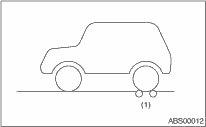
2. Set the front wheels or rear wheels on the brake tester and set the select lever position to the “N” range.
|
(1) |
Brake tester |
3. Operate the brake tester.
4. Perform ABS sequence control.
5. When the VDCH/U begins to work, check the working sequence in the following order.
(1) The FL wheel performs decompression, hold and compression in sequence, and subsequently the FR wheel repeats the cycle.
(2) The RR wheel performs decompression, hold and compression in sequence, and subsequently the RL wheel repeats the cycle.
6. Read values indicated on the brake tester and check if the fluctuation of the values between decompression and compression meets specification.
|
Front wheel |
Rear wheel | |
|
When pressurized |
2,000 N (203 kgf, 447 lbf) or more |
1,000 N (102 kgf, 224 lbf) or more |
|
When depressurized |
500 N (51 kgf, 112 lbf) or less |
500 N (51 kgf, 112 lbf) or less |
7. After inspection, check whether any irregular brake pedal tightness cab be felt.