Check the following items before performing the wheel alignment measurement.
Check items before measuring wheel alignment:
• Tire inflation pressure
• Uneven wear of RH and LH tires, or difference of sizes
• Tire runout
• Excessive play and wear of ball joint
• Excessive play and wear of tie rod end
• Excessive play of wheel bearing
• Right and left wheel base imbalance
• Deformation and excessive play of steering link
• Deformation and excessive play of suspension parts
Check, adjust and measure the wheel alignment in accordance with the procedures indicated in the figure.
|
Wheel arch height (front and rear wheels)
|
|
↓ |
|
Camber (front and rear wheels)
|
|
↓ |
|
Caster (front wheel)
|
|
↓ |
|
Steering angle
|
|
↓ |
|
Front wheel toe-in
|
|
↓ |
|
REAR Wheel Toe-In
|
|
↓ |
|
Thrust angle
|
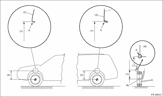
1. Park the vehicle on a level surface.
2. Empty the vehicle so that it is at “curb weight”. (Empty the luggage compartment, load the spare tire, jack and service tools, and fill up the fuel tank.)
3. Set the steering wheel in a straight-ahead position, and stabilize the suspensions by moving the vehicle in a straight line for 5 m (16 ft) or more.
4. Suspend a thread from the wheel arch (point “A” in the figure below) and affix at a position directly above the center of wheel.
5. Measure the distance between the point “A” and the center of wheel.
|
(1) |
Wheel arch height |
(4) |
Front wheel arch height |
(7) |
Point of measurement |
|
(2) |
Front fender |
(5) |
Rear wheel arch height |
(8) |
End of spindle |
|
(3) |
Rear quarter |
(6) |
Flange bend line |
|
Model |
Specified wheel arch height | |
|
Front |
Rear | |
|
Non-turbo |
437+12/−24 mm (17.20+0.47/−0.94 in) |
440+12/−24 mm (17.32+0.47/−0.94 in) |
|
Turbo |
435+12/−24 mm (17.13+0.47/−0.94 in) | |
INSPECTION
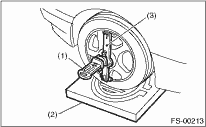
1. Place the front wheel on the turning radius gauge. Make sure the ground contact surfaces of the front and rear wheels are at the same height.
2. Set the adapter into the center of wheel, and then set the wheel alignment gauge.
|
(1) |
Alignment gauge |
|
(2) |
Turning radius gauge |
|
(3) |
Adapter |
3. Measure the camber angle in accordance with the operation manual for wheel alignment gauge.
|
Model |
Camber (Difference between RH and LH: 45′ or less) | |
|
Front |
Non-turbo, Turbo |
−0°25′±0°45′ |
|
Rear |
Non-turbo |
−0°50′±0°45′ |
|
Turbo |
−0°55′±0°45′ | |
FRONT CAMBER ADJUSTMENT
1. When adjusting the camber, adjust it to the following value.
|
Model |
Camber (Difference between RH and LH: 45′ or less) | |
|
Front |
Non-turbo, Turbo |
−0°25′±0°30′ |
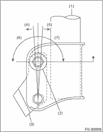
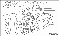
2. Loosen the two self-locking nuts located at the front lower section of the strut.
NOTE:
When the adjusting bolt needs to be loosened or tightened, hold its head with a wrench and turn the self-locking nut.
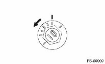
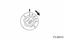
3. Turn the camber adjusting bolt so that the camber is set at specification.
NOTE:
Moving the adjusting bolt by one scale changes the camber by approximately 0°10′.
|
(1) |
Strut |
|
(2) |
Adjusting bolt |
|
(3) |
Housing |
|
(4) |
Outer |
|
(5) |
Inner |
|
(6) |
Camber is increased. |
|
(7) |
Camber is decreased. |
|
To increase camber. | |
|
Rotate the left side counterclockwise. |
Rotate the right side clockwise. |
|
|
|
|
To decrease camber. | |
|
Rotate the left side clockwise. |
Rotate the right side counterclockwise. |
|
|
|
4. Tighten two new self-locking nuts.
Tightening torque:
175 N·m (17.8 kgf-m, 129 ft-lb)
INSPECTION
1. Place the front wheel on the turning radius gauge. Make sure the ground contact surfaces of the front and rear wheels are at the same height.
2. Set the adapter into the center of wheel, and then set the wheel alignment gauge.
|
(1) |
Alignment gauge |
|
(2) |
Turning radius gauge |
|
(3) |
Adapter |
3. Measure the caster angle in accordance with the operation manual for wheel alignment gauge.
|
Model |
Caster | |
|
All models |
3°03′ | |
INSPECTION
1. Place the vehicle on turning radius gauge.
2. While depressing the brake pedal, turn the steering wheel fully to the left and right. With the steering wheel held at each fully turned position, measure both the inner and outer wheel steering angles.
Steering angle:
|
Model |
Non-turbo |
Turbo |
|
Inner wheel |
36°25′±1°30′ |
35°00′±1°30′ |
|
Outer wheel |
32°00′±1°30′ |
30°54′±1°30′ |
ADJUSTMENT
1. Turn the tie-rod to adjust the steering angle of both inner and outer wheels.
2. Check the toe-in.
NOTE:
Correct the boot if it is twisted.
|
(1) |
Lock nut |
INSPECTION
Toe-in (tolerance):
0±3 mm (0±0.12 in)
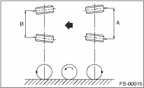
1. Set the toe-in gauge at the height of wheel axis center, behind the right and left front tires.
2. Mark the centers of both right and left tires, and measure the distance “A” between the marks.
3. Move the vehicle forward to rotate the tires 180°.
NOTE:
Be sure to rotate the tires in the forward direction.
4. Measure the distance “B” between the left and right marks. Find toe-in using the following calculation:
A − B = Toe-in
ADJUSTMENT
When adjusting the toe-in, adjust it to the following value.
Toe-in (adjustment standard):
0±2 mm (0±0.08 in)
1. Check that the left and right wheel steering angles are within specification.
2. Loosen the left and right side steering tie-rod lock nuts.
3. Turn the left and right tie-rods by equal amounts until the toe-in is at the specification.
Both the left and right tie-rods are right-hand threaded. To increase toe-in, turn both tie-rods clockwise by equal amount (viewing from the inside of vehicle).
|
(1) |
Lock nut |
4. Tighten the tie-rod lock nut.
Tightening torque:
85 N·m (8.7 kgf-m, 63 ft-lb)
NOTE:
Check and correct the tie rod boot if twisted.
INSPECTION
Toe-in (tolerance):
2±3 mm (0.079±0.118 in)
Refer to FRONT WHEEL TOE-IN for rear toe-in inspection procedures.

ADJUSTMENT
When adjusting the toe-in, adjust it to the following value.
Toe-in (adjustment standard):
2±2 mm (0.079±0.079 in)
1. Loosen the self-locking nut on the inner side of link rear.
NOTE:
When loosening or tightening the adjusting bolt, hold the bolt head and turn the self-locking nut.
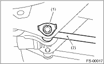
|
(1) |
Adjusting bolt |
|
(2) |
Link rear |
2. Turn the adjusting bolt until toe-in is within the specification.
NOTE:
When the left and right wheels are adjusted for toe-in at the same time, the movement of one scale graduation changes toe-in by approx. 1.5 mm (0.6 in).
|
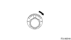
To increase toe-in. | |
|
Rotate the left side clockwise. |
Rotate the right side counterclockwise. |
|
|
|
|
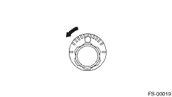
To decrease toe-in. | |
|
Rotate the left side counterclockwise. |
Rotate the right side clockwise. |
|
|
|
3. Replace with a new self-locking nut and tighten.
Tightening torque:
100 N·m (10.2 kgf-m, 74 ft-lb)
INSPECTION
1. Park the vehicle on a level surface.
2. Move the vehicle 3 to 4 meters (10 to 13 feet) straight forward.
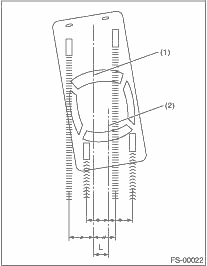
3. Draw the center of loci for both the front and rear axles.
4. Measure distance “L” between the center lines of the axle loci.
Thrust angle
0°±30′
(Less than 30′ when “L” is 23 mm (0.9 in) or less.)
|
(1) |
Center line of loci (front axle) |
|
(2) |
Center line of loci (rear axle) |
ADJUSTMENT
When adjusting, adjust it to the following value.
Thrust angle
0°±20′
(Less than 20′ when “L” is 15 mm (0.6 in) or less.)
1. Make thrust angle adjustments by turning the toe-in adjusting bolts of the rear suspension equally in the same direction.
2. In the same order of making the thrust angle adjustment when one rear wheel is adjusted in a toe-in direction, adjust the other rear wheel equally in toe-out direction.
3. When the left and right adjusting bolts are turned by one graduation, the thrust angle will change approx. 20′. [“L”: Approximately 15 mm (0.591 in)
|
(1) |
Center line of loci (front axle) |
|
(2) |
Center line of loci (rear axle) |
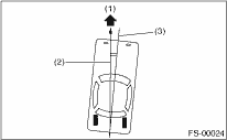
NOTE:
The thrust angle is the average value of the right and left wheel toe angles with regard to the center line of the body. The vehicle will advance towards the thrust angle direction while swaying in a angle direction.
|
(1) |
Front |
|
(2) |
Thrust angle |
|
(3) |
Body center line |
Thrust angle: γ = (α - β)/2
α: Rear RH wheel toe-in angle
β: Rear LH wheel toe-in angle
Substitute only the positive toe-in values from each wheel into α and β in the calculation.
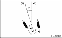
|
(1) |
Front |
|
(2) |
Body center line |