1. Visually check for cracks and damage. Use liquid penetrant tester on the important sections to check for fissures.
2. Check the oil passages for clogging.
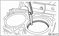
3. Inspect the cylinder head surface that mates with cylinder block for warping by using a straight edge, and correct by grinding if necessary.
Warping limit:
0.025 mm (0.00098 in)
Grinding limit:
0.1 mm (0.004 in)
Standard height of cylinder block:
201.0 mm (7.91 in)
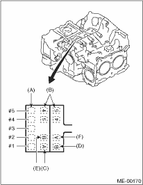
1. The cylinder bore size is stamped on the cylinder block front upper surface.
NOTE:
• Measurement should be performed at a temperature of 20°C (68°F).
• Standard sized pistons are classified into two grades, “A” and “B”. These grades should be used as guide lines in selecting a standard piston.
Standard diameter:
DOHC Non-turbo model
A: 92.005 — 92.015 mm (3.6222 — 3.6226 in)
B: 91.995 — 92.005 mm (3.6218 — 3.6222 in)
DOHC Turbo model
A: 99.505 — 99.515 mm (3.9175 — 3.9179 in)
B: 99.495 — 99.505 mm (3.9171 — 3.9175 in)
|
(A) |
Main journal size mark |
|
(B) |
Cylinder block (RH) —(LH) combination mark |
|
(C) |
#1 cylinder bore size mark |
|
(D) |
#2 cylinder bore size mark |
|
(E) |
#3 cylinder bore size mark |
|
(F) |
#4 cylinder bore size mark |
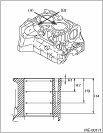
2. How to measure the inner diameter of each cylinder:
Measure the inner diameter of each cylinder in both the thrust and piston pin directions at the heights as shown in the figure, using a cylinder bore gauge.
NOTE:
Measurement should be performed at a temperature of 20°C (68°F).
Taper:
Standard:
0.015 mm (0.0006 in)
Service limit:
0.050 mm (0.0020 in)
Out-of-roundness:
Standard:
0.010 mm (0.0004 in)
Service limit:
0.050 mm (0.0020 in)
|
(A) |
Piston pin direction |
|
(B) |
Thrust direction |
|
H1: |
10 mm (0.39 in) |
|
H2: |
45 mm (1.77 in) |
|
H3: |
80 mm (3.15 in) |
|
H4: |
115 mm (4.53 in) |
3. When the piston is to be replaced due to general or cylinder wear, determine a suitable sized piston by measuring the piston clearance.
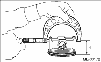
4. How to measure the outer diameter of each piston:
Measure the outer diameter of each piston at the height as shown in the figure. (Thrust direction)
NOTE:
Measurement should be performed at a temperature of 20°C (68°F).
Piston grade point H:
DOHC Non-turbo model
40.0 mm (1.57 in)
DOHC Turbo model
38.2 mm (1.50 in)
Piston outer diameter:
DOHC Non-turbo model
Standard:
A: 92.005 — 92.015 mm (3.6222 — 3.6226 in)
B: 91.995 — 92.005 mm (3.6219 — 3.6222 in)
0.25 mm (0.0098 in) oversize:
92.245 — 92.265 mm (3.6317 — 3.6467 in)
0.50 mm (0.0197 in) oversize:
92.495 — 92.515 mm (3.6415 — 3.6423 in)
DOHC Turbo model
Standard:
A: 99.505 — 99.515 mm (3.9175 — 3.9179 in)
B: 99.495 — 99.505 mm (3.9171 — 3.9175 in)
0.25 mm (0.0098 in) oversize:
99.745 — 99.765 mm (3.9270 — 3.9278 in)
0.50 mm (0.0197 in) oversize:
99.995 — 100.015 mm (3.9368 — 3.9376 in)
5. Calculate the clearance between cylinder and piston.
NOTE:
Measurement should be performed at a temperature of 20°C (68°F).
Cylinder to piston clearance at 20°C (68°F):
Standard:
−0.010 — 0.010 mm (−0.0004 — 0.0004 in)
Service limit:
0.030 mm (0.0012 in)
6. Boring and honing:
(1) If any of the value of taper, out-of-roundness, or cylinder-to-piston clearance measured exceeds the specified limit or if there is any damage on the cylinder wall, rebore it for replacement with an oversize piston.
CAUTION:
• When any of the cylinders needs reboring, all other cylinders must be bored at the same time, and replaced with oversize pistons.
• Do not perform boring on one cylinder only. Do not replace only a single cylinder for an oversize piston.
(2) If the cylinder inner diameter exceeds the limit after boring and honing, replace the cylinder block.
NOTE:
Immediately after reboring, the cylinder diameter may differ from its real diameter due to temperature rise. Thus, when measuring the cylinder diameter, wait until it has cooled to room temperature.
Limit of cylinder boring (diameter):
DOHC Non-turbo model
92.505 mm (3.642 in)
DOHC Turbo model
100.005 mm (3.937 in)
1. Check the piston and piston pin for breaks, cracks or wear. Replace if faulty.
2. Check the piston ring groove for wear and damage. Replace if faulty.
3. Measure the piston-to-cylinder clearance at each cylinder.  If any of the clearances exceeds the limit, replace the piston with an oversize piston and bore the cylinder.
4. Make sure that the piston pin can be inserted into the piston pin hole with a thumb at 20°C (68°F). Replace if faulty.
Standard clearance between piston pin and hole in piston:
Standard:
0.004 — 0.008 mm (0.0002 — 0.0003 in)
Service limit:
0.020 mm (0.0008 in)
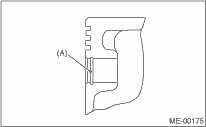
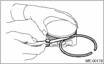
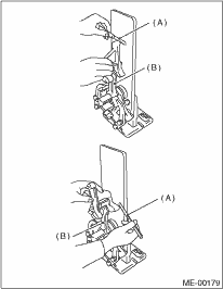
5. Check the snap ring installation groove (A) on the piston for burr. If necessary, remove burr from the groove so that the piston pin can lightly move.
6. Check the piston pin snap ring for distortion, cracks and wear.
1. If the piston ring is broken, damaged or worn, or if its tension is insufficient, or when the piston is replaced, replace the piston ring with a new part of the same size as piston.
NOTE:
• Marks are shown on the end of top and second rings. When installing them to piston, face this mark upward.
• Oil ring consists of the upper rail, expander and lower rail. When installing oil ring on piston, be careful of the direction of each rails.
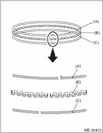
|
(A) |
Upper rail |
|
(B) |
Expander |
|
(C) |
Lower rail |
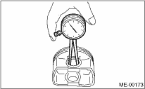
2. Squarely place the piston ring and oil ring in cylinder using the piston, and measure the piston ring gap with a thickness gauge.
• DOHC Non-turbo model
|
Unit: mm (in) | |||
|
Standard |
Limit | ||
|
Ring closed gap |
Top ring |
0.20 — 0.30 (0.0079 — 0.0118) |
1.0 (0.039) |
|
Second ring |
0.40 — 0.50 (0.0157 — 0.0197) |
1.0 (0.039) | |
|
Oil ring rail |
0.20 — 0.50 (0.0079 — 0.0197) |
1.5 (0.059) | |
• DOHC Turbo model
|
Unit: mm (in) | |||
|
Standard |
Limit | ||
|
Ring closed gap |
Top ring |
0.20 — 0.25 (0.0079 — 0.0098) |
1.0 (0.039) |
|
Second ring |
0.37 — 0.52 (0.015 — 0.020) |
1.0 (0.039) | |
|
Oil ring rail |
0.20 — 0.50 (0.0079 — 0.0197) |
1.5 (0.059) | |
3. Fit the piston ring straight into the piston ring groove, then measure the clearance between piston ring and piston ring groove with a thickness gauge.
NOTE:
Before measuring the clearance, clean the piston ring groove and piston ring.
• DOHC Non-turbo model
|
Unit: mm (in) | |||
|
Standard |
Limit | ||
|
Ring groove gap |
Top ring |
0.040 — 0.080 (0.0016 — 0.0031) |
0.15 (0.0059) |
|
Second ring |
0.030 — 0.070 (0.0012 — 0.0028) |
0.15 (0.0059) | |
• DOHC Turbo model
|
Unit: mm (in) | |||
|
Standard |
Limit | ||
|
Ring groove gap |
Top ring |
0.040 — 0.080 (0.0016 — 0.0031) |
0.15 (0.0059) |
|
Second ring |
0.030 — 0.070 (0.0012 — 0.0028) |
0.15 (0.0059) | |
1. Replace the connecting rod, if the large or small end thrust surface is damaged.
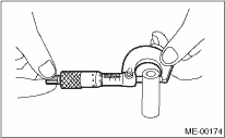
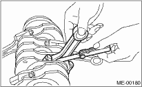
2. Check for bend or twist using a connecting rod aligner. Replace the connecting rod if the bend or twist exceeds the limit.
Limit of bend or twist per 100 mm (3.94 in) in length:
0.10 mm (0.0039 in)
|
(A) |
Thickness gauge |
|
(B) |
Connecting rod |
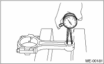
3. Install the connecting rod fitted with bearing to the crankshaft and measure the side clearance (thrust clearance) using a thickness gauge. Replace the connecting rod if the side clearance exceeds the specified limit.
Connecting rod side clearance:
Standard:
0.070 — 0.330 mm (0.0028 — 0.0130 in)
Service limit:
0.4 mm (0.016 in)
4. Inspect the connecting rod bearing for scar, peeling, seizure, melting, wear, etc.
5. Measure the oil clearance on each connecting rod bearing using plastigauge. If any oil clearance is not within specification, replace the defective bearing with a new part of standard size or undersize as necessary. (See the table below.)
Connecting rod oil clearance:
DOHC Non-turbo model
Standard:
0.016 — 0.044 mm (0.00063 — 0.0017 in)
Service limit:
0.05 mm (0.0020 in)
|
Unit: mm (in) | ||
|
Bearing |
Bearing size (Thickness at center) |
Outer diameter of crank pin |
|
Standard |
1.492 — 1.501 (0.0587 — 0.0591) |
51.984 — 52.000 (2.0466 — 2.0472) |
|
0.03 (0.0012) undersize |
1.510 — 1.513 (0.0594 — 0.0596) |
51.954 — 51.970 (2.0454 — 2.0461) |
|
0.05 (0.0020) undersize |
1.520 — 1.523 (0.0599 — 0.0600) |
51.934 — 51.950 (2.0447 — 2.0453) |
|
0.25 (0.0098) undersize |
1.620 — 1.623 (0.0638 — 0.0639) |
51.734 — 51.750 (2.0368 — 2.0374) |
Connecting rod oil clearance:
DOHC Turbo model:
Standard:
0.017 — 0.045 mm (0.0007 — 0.0018 in)
Service limit:
0.05 mm (0.0020 in)
|
Unit: mm (in) | ||
|
Bearing |
Bearing size (Thickness at center) |
Outer diameter of crank pin |
|
Standard |
1.490 — 1.502 (0.0587 — 0.0591) |
51.984 — 52.000 (2.0466 — 2.0472) |
|
0.03 (0.0012) undersize |
1.504 — 1.512 (0.0592 — 0.0595) |
51.954 — 51.970 (2.0454 — 2.0461) |
|
0.05 (0.0020) undersize |
1.514 — 1.522 (0.0596 — 0.0599) |
51.934 — 51.950 (2.0447 — 2.0453) |
|
0.25 (0.0098) undersize |
1.614 — 1.622 (0.0635 — 0.0639) |
51.734 — 51.750 (2.0368 — 2.0374) |
6. Inspect the bushing at connecting rod small end, and replace with a new part if worn or damaged.
7. Measure the piston pin clearance at connecting rod small end. Replace it with a new part if the limit has been exceeded.
Clearance between piston pin and bushing:
Standard:
0 — 0.022 mm (0 — 0.0009 in)
Service limit:
0.030 mm (0.0012 in)
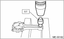
8. The replacement procedure for the connecting rod small end bushing is as follows.
(1) Remove the bushing from connecting rod with ST and press.
(2) Press the bushing with the ST after applying oil on the periphery of new bushing.
| ST 499037100 | CONNECTING ROD BUSHING REMOVER AND INSTALLER |
(3) Make two holes with 3 mm (0.12 in) diameter on the pressed-fit bushing so that the they match with the machined hole of the connecting rod, and ream the inside of bushing.
(4) After completion of reaming, clean the bushing to remove chips.
6. CRANKSHAFT AND CRANKSHAFT BEARING
1. Clean the crankshaft completely, and check it for cracks through liquid penetrant testing, etc. If faulty, replace with new a new crankshaft.
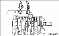
2. Measure the bend of crankshaft. If it exceeds the limit, correct or replace it.
NOTE:
If a suitable V-block is not available, using just the #1 and #5 crankshaft bearings on cylinder block, position the crankshaft on cylinder block. Then, measure the crankshaft bend using a dial gauge.
Crankshaft bend limit:
0.035 mm (0.0014 in)
3. Inspect the crank journal and crank pin for wear. If they are not within the specification, replace the bearing with a suitable (undersize) one, and replace or grind to correct the crankshaft as necessary. When grinding the crank journal or crank pin, finish them to the specified dimensions according to the undersize bearing to be used.
Crank pin:
Out-of-roundness:
DOHC Non-turbo model
0.005 mm (0.0002 in)
DOHC Turbo model
0.003 mm (0.0001 in)
Cylindricality:
DOHC Non-turbo model
0.006 mm (0.0002 in)
DOHC Turbo model
0.004 mm (0.0002 in)
Grinding limit:
To 51.750 mm (2.0374 in) dia.
Crank journal:
Out-of-roundness:
0.005 mm (0.0002 in)
Cylindricality:
0.006 mm (0.0002 in)
Grinding limit:
To 59.758 mm (2.3527 in) dia.
• DOHC Non-turbo model
|
Unit: mm (in) | ||||
|
Crank journal outer diameter |
Crank pin outer diameter | |||
|
#1, #3 |
#2, #4, #5 | |||
|
Standard |
Journal O.D. |
59.992 — 60.008 (2.3619 — 2.3625) |
59.992 — 60.008 (2.3619 — 2.3625) |
51.984 — 52.000 (2.0466 — 2.0472) |
|
Bearing size (Thickness at center) |
1.998 — 2.011 (0.0787 — 0.0792) |
2.000 — 2.013 (0.0787 — 0.0793) |
1.492 — 1.501 (0.0587 — 0.0591) | |
|
0.03 (0.0012) undersize |
Journal O.D. |
59.962 — 59.978 (2.3607 — 2.3613) |
59.962 — 59.978 (2.3607 — 2.3613) |
51.954 — 51.970 (2.0454 — 2.0461) |
|
Bearing size (Thickness at center) |
2.017 — 2.020 (0.0794 — 0.0795) |
2.019 — 2.022 (0.0795 — 0.0796) |
1.510 — 1.513 (0.0594 — 0.0596) | |
|
0.05 (0.0020) undersize |
Journal O.D. |
59.942 — 59.958 (2.3599 — 2.3605) |
59.942 — 59.958 (2.3599 — 2.3605) |
51.934 — 51.950 (2.0447 — 2.0453) |
|
Bearing size (Thickness at center) |
2.027 — 2.030 (0.0798 — 0.0799) |
2.029 — 2.032 (0.0799 — 0.0800) |
1.520 — 1.523 (0.0599 — 0.0600) | |
|
0.25 (0.0098) undersize |
Journal O.D. |
59.742 — 59.758 (2.3520 — 2.3527) |
59.742 — 59.758 (2.3520 — 2.3527) |
51.734 — 51.750 (2.0368 — 2.0374) |
|
Bearing size (Thickness at center) |
2.127 — 2.130 (0.0837 — 0.0839) |
2.129 — 2.132 (0.0838 — 0.0839) |
1.620 — 1.623 (0.0638 — 0.0639) | |
• DOHC Turbo model
|
Unit: mm (in) | ||||
|
Crank journal outer diameter |
Crank pin outer diameter | |||
|
#1, #3 |
#2, #4, #5 | |||
|
Standard |
Journal O.D. |
59.992 — 60.008 (2.3619 — 2.3625) |
59.992 — 60.008 (2.3619 — 2.3625) |
51.984 — 52.000 (2.0466 — 2.0472) |
|
Bearing size (Thickness at center) |
1.998 — 2.011 (0.0787 — 0.0792) |
2.000 — 2.013 (0.0787 — 0.0793) |
1.490 — 1.502 (0.0587 — 0.0591) | |
|
0.03 (0.0012) undersize |
Journal O.D. |
59.962 — 59.978 (2.3607 — 2.3613) |
59.962 — 59.978 (2.3607 — 2.3613) |
51.954 — 51.970 (2.0454 — 2.0461) |
|
Bearing size (Thickness at center) |
2.017 — 2.020 (0.0794 — 0.0795) |
2.019 — 2.022 (0.0795 — 0.0796) |
1.504 — 1.512 (0.0592 — 0.0595) | |
|
0.05 (0.0020) undersize |
Journal O.D. |
59.942 — 59.958 (2.3599 — 2.3605) |
59.942 — 59.958 (2.3599 — 2.3605) |
51.934 — 51.950 (2.0447 — 2.0453) |
|
Bearing size (Thickness at center) |
2.027 — 2.030 (0.0798 — 0.0799) |
2.029 — 2.032 (0.0799 — 0.0800) |
1.514 — 1.522 (0.0596 — 0.0599) | |
|
0.25 (0.0098) undersize |
Journal O.D. |
59.742 — 59.758 (2.3520 — 2.3527) |
59.742 — 59.758 (2.3520 — 2.3527) |
51.734 — 51.750 (2.0368 — 2.0374) |
|
Bearing size (Thickness at center) |
2.127 — 2.130 (0.0837 — 0.0839) |
2.129 — 2.132 (0.0838 — 0.0839) |
1.614 — 1.622 (0.0635 — 0.0639) | |
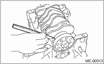
4. Use a thickness gauge to measure the thrust clearance of crankshaft at center bearing. If the clearance exceeds the limit, replace the bearing.
Crankshaft thrust clearance:
Standard:
0.030 — 0.115 mm (0.0012 — 0.0045 in)
Service limit:
0.25 mm (0.0098 in)
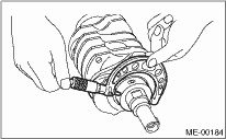
5. Inspect individual crankshaft bearings for signs of flaking, seizure, melting and wear.
6. Measure the oil clearance on each crankshaft bearing using plastigauge. If the measurement exceeds the limit, replace the defective bearing with an undersize one, and replace or recondition the crankshaft as necessary.
Crankshaft oil clearance:
Standard:
0.010 — 0.030 mm (0.0004 — 0.0012 in)
Service limit:
0.040 mm (0.0016 in)