|
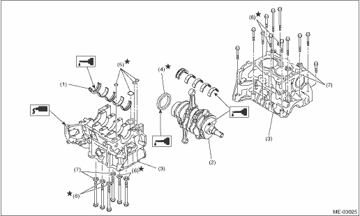
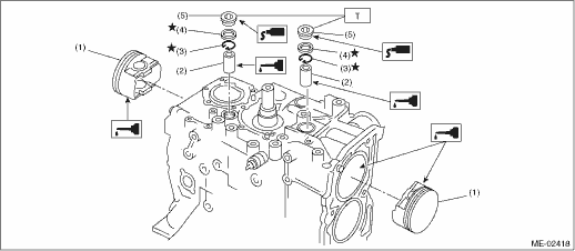
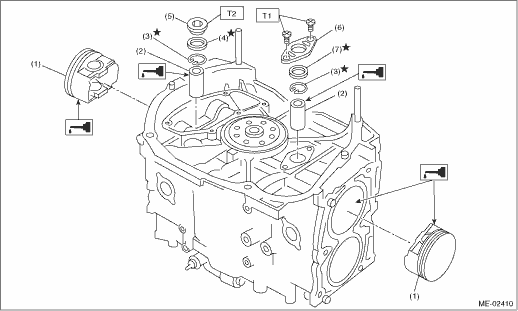
(1) |
Crankshaft bearing |
(4) |
Rear oil seal |
(6) |
Seal washer |
|
(2) |
Crankshaft |
(5) |
O-ring |
(7) |
Washer |
|
(3) |
Cylinder block |
1. Remove oil on the mating surface of cylinder block before installation. Apply engine oil on bearings and crankshaft journals.
2. Position the crankshaft and O-rings on #1 and #3 cylinder block.
3. Apply liquid gasket to the mating surface of #1 and #3 cylinder blocks, and position it on cylinder block #2 and #4.
Liquid gasket:
THREE BOND 1215 (Part No. 004403007) or equivalent
NOTE:
Do not allow liquid gasket to jut into O-ring grooves, oil passages, bearing grooves, etc.
4. Apply a coat of engine oil to the washer and bolt threads.
NOTE:
Use a new seal washer.
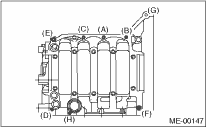
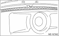
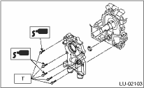
5. Tighten the 10 mm cylinder block connecting bolts on the LH side (A — D) in alphabetical order.
Tightening torque:
10 N·m (1.0 kgf-m, 7.4 ft-lb)
6. Tighten the 10 mm cylinder block connecting bolts on the RH side (E — J) in alphabetical order.
Tightening torque:
10 N·m (1.0 kgf-m, 7.4 ft-lb)
7. Tighten the LH side cylinder block connecting bolts (A — D) further in alphabetical order.
Tightening torque:
18 N·m (1.8 kgf-m, 13.3 ft-lb)
8. Tighten the RH side cylinder block connecting bolts (E — J) further in alphabetical order.
Tightening torque:
18 N·m (1.8 kgf-m, 13.3 ft-lb)
9. Tighten the LH side cylinder block connecting bolts (A — D) further in alphabetical order.
• (A), (C): Angle tightening
Tightening angle:
90°
• (B), (D): Torque tightening
Tightening torque:
40 N·m (4.1 kgf-m, 29.6 ft-lb)
10. Tighten the RH side cylinder block connecting bolts (E — J) 90° further in alphabetical sequence.
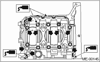
11. Tighten the 8 mm and 6 mm cylinder block connecting bolts on LH side (A — H) in alphabetical sequence.
Tightening torque:
(A) — (G): 25 N·m (2.5 kgf-m, 18.4 ft-lb)
(H): 6.4 N·m (0.65 kgf-m, 4.7 ft-lb)
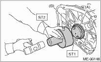
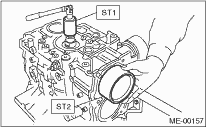
12. Apply a coat of engine oil to the periphery of oils seal and install the rear oil seals using ST1 and ST2.
NOTE:
Use a new rear oil seal.
| ST1 499597100 | CRANKSHAFT OIL SEAL GUIDE |
| ST2 499587200 | CRANKSHAFT OIL SEAL INSTALLER |
|
(A) |
Rear oil seal |
|
(B) |
Flywheel attaching bolt |
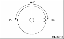
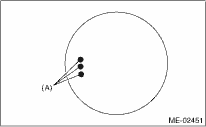
13. Position the top ring gap at (A) or (B) in the figure.
14. Position the second ring gap at 180° on the reverse side the top ring gap.
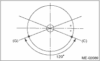
15. Position the upper rail gap at (C) in the figure.
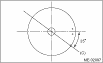
16. Align the upper rail spin stopper (E) to the side hole (D) on the piston.
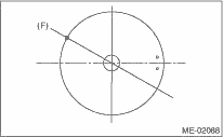
17. Position the expander gap at (F) in the figure on the 180° opposite direction of (C).
18. Set the lower rail gap at position (G), located 120° clockwise from (c).
NOTE:
• Make sure ring gaps do not face the same direction.
• Make sure ring gaps are not within the piston skirt area.
19. Install the snap ring.
Install the snap rings in the piston holes located opposite to the service holes in cylinder block before positioning all pistons in the cylinder blocks.
NOTE:
Use new snap rings.
|
(A) |
Front side |
|
(1) |
Piston |
(4) |
Gasket |
Tightening torque:N·m (kgf-m, ft-lb) | |
|
(2) |
Piston pin |
(5) |
Service hole plug |
T: |
70 (7.1, 51.6) |
|
(3) |
Snap ring |
||||
20. Install the piston.
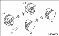
(1) Place the cylinder block to face the #1 and #2 cylinder side upward.
(2) Using the ST1, turn the crankshaft so that #1 and #2 connecting rods are set at bottom dead center.
| ST1 499987500 | CRANKSHAFT SOCKET |
(3) Apply a coat of engine oil to the pistons and cylinders and insert pistons in their cylinders using ST2.
| ST2 498747300 | PISTON GUIDE |
NOTE:
Face the piston front mark towards the front of the engine.
|
(A) |
Front mark |
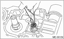
21. Install the piston pin.
(1) Apply a coat of engine oil to ST3.
(2) Insert ST3 into the service hole to align piston pin hole with connecting rod small end.
| ST3 499017100 | PISTON PIN GUIDE |
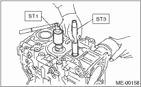
(3) Apply a coat of engine oil to piston pin, and insert the piston pin into piston and connecting rod through service hole.
(4) Install the snap ring.
NOTE:
Use new snap rings.
(5) Apply liquid gasket on the threaded portion of the service hole plug.
Liquid gasket:
THREE BOND 1105 (Part No. 004403010) or equivalent
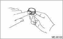
(6) Install the service hole plug and gasket.
NOTE:
Use a new gasket.
|
(1) |
Piston |
(5) |
Service hole plug |
Tightening torque:N·m (kgf-m, ft-lb) | |
|
(2) |
Piston pin |
(6) |
Service hole cover |
T1: |
6.4 (0.65, 4.7) |
|
(3) |
Snap ring |
(7) |
O-ring |
T2: |
70 (7.1, 51.6) |
|
(4) |
Gasket |
||||
(7) Place the cylinder block to face the #3 and #4 cylinder side upward. Following the same procedures as used for #1 and #2 cylinders, install the pistons and piston pins.
22. Install the water pipe.
Tightening torque:
6.4 N·m (0.65 kgf-m, 4.7 ft-lb)
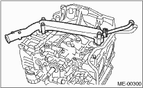
23. Install the baffle plate.
Tightening torque:
6.4 N·m (0.65 kgf-m, 4.7 ft-lb)
24. Install the oil strainer and O-ring.
Tightening torque:
10 N·m (1.0 kgf-m, 7.4 ft-lb)
25. Install the oil strainer stay.
NOTE:
Tighten the oil strainer stay and baffle plate together.
Tightening torque:
6.4 N·m (0.65 kgf-m, 4.7 ft-lb)
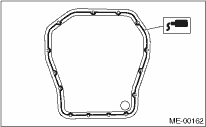
26. Apply liquid gasket to the mating surfaces, and install the oil pan.
NOTE:
Install within 3 min. after applying liquid gasket.
Liquid gasket:
THREE BOND 1207C (Part No. 004403012) or equivalent
Tightening torque:
5 N·m (0.5 kgf-m, 3.6 ft-lb)
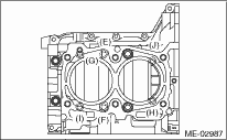
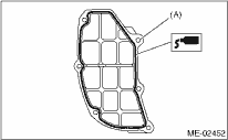
27. Apply liquid gasket to the mating surfaces and the threaded portion of bolt (A) shown in the figure (when bolt is reused), and then install the oil separator cover.
NOTE:
Install within 3 min. after applying liquid gasket.
Liquid gasket:
• Mating surface
THREE BOND 1217G or equivalent
• Threaded portion of bolt (A) (when bolt is reused)
THREE BOND 1324 (Part No. 004403042) or equivalent
Tightening torque:
6.4 N·m (0.65 kgf-m, 4.7 ft-lb)
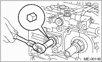
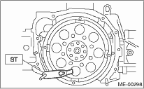
28. Install the flywheel. (MT model)

To lock the crankshaft, use the ST.
| ST 498497100 | CRANKSHAFT STOPPER |
Tightening torque:
72 N·m (7.3 kgf-m, 52.8 ft-lb)
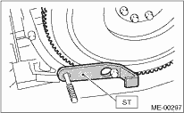
29. Install the drive plate. (AT model)
To lock the crankshaft, use the ST.
| ST 498497100 | CRANKSHAFT STOPPER |
Tightening torque:
72 N·m (7.3 kgf-m, 52.8 ft-lb)
30. Install the housing cover.
31. Installation of oil pump:
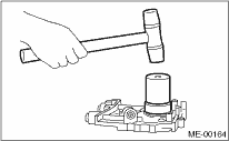
(1) Replace the front oil seal with a new part using ST.
| ST 499587100 | OIL SEAL INSTALLER |
(2) Apply liquid gasket to the matching surface of oil pump.
Liquid gasket:
THREE BOND 1215 (Part No. 004403007) or equivalent
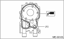
|
(A) |
O-ring |
(3) Apply a coat of engine oil to the inside of oil seal.
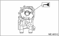
(4) Install the oil pump to cylinder block. Be careful not to damage the oil seal during installation.
NOTE:
• Make sure the oil seal lip is not folded.
• Align the flat surface of oil pump’s inner rotor with crankshaft before installation.
• Use O-ring and oil seal when installing the oil pump.
(5) Apply liquid gasket to the three bolts thread shown in figure. (when bolts are reused)
Liquid gasket:
THREE BOND 1324 (Part No. 004403042) or equivalent
Tightening torque:
6.4 N·m (0.65 kgf-m, 4.7 ft-lb)
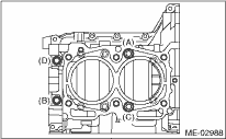
32. Install the water pump and gasket.
Tightening torque:
First: 12 N·m (1.2 kgf-m, 8.7 ft-lb)
Second: 12 N·m (1.2 kgf-m, 8.7 ft-lb)
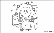
NOTE:
• When installing the water pump, tighten bolts in two stages in alphabetical sequence as shown in the figure.
• Use a new gasket.
33. Install the water by-pass pipe for heater.
34. Install the oil filter.
35. Tighten the cylinder head bolts.
36. Install the oil level gauge guide and tighten the bolts. (LH side only)
37. Install the crank sprocket.
38. Install the cam sprocket.
39. Install the timing belt.
40. Adjust the valve clearance.
41. Install the rocker cover with the rocker cover gasket to the cylinder head, and then connect the PCV hose.
NOTE:
Use a new rocker cover gasket and rocker cover washers.
42. Install the timing belt cover.
43. Install the crank pulley.
44. Install the intake manifold.
45. Install the generator and A/C compressor brackets on cylinder head.
46. Install the V-belts.