1.CHECK OUTPUT SIGNAL OF ECM.
1) Turn the ignition switch to OFF.
2) Connect the test mode connector at the lower portion of instrument panel (on the driver’s side).
3) Turn the ignition switch to ON.
4) Measure the voltage between ECM and chassis ground while operating the radiator fan relay.
NOTE:
The radiator fan relay can be operated using the Subaru Select Monitor. Regarding the procedures, refer to “Compulsory Valve Operation Check Mode”. 
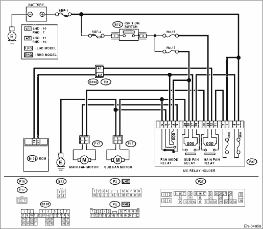
Connector & terminal
(B135) No. 19 (+) — Chassis ground (−):
(B135) No. 27 (+) — Chassis ground (−):
|
|
Even if the malfunction indicator light illuminates, the circuit has returned to a normal condition at this time. In this case, repair the poor contact in ECM connector.
|
|
2.CHECK SHORT CIRCUIT OF RADIATOR FAN RELAY CONTROL.
1) Turn the ignition switch to OFF.
2) Remove the main fan relay and sub fan relay. (Model with A/C)
3) Disconnect the test mode connector.
4) Turn the ignition switch to ON.
5) Measure the voltage between ECM and chassis ground.
Connector & terminal
(B135) No. 19 (+) — Chassis ground (−):
(B135) No. 27 (+) — Chassis ground (−):
|
Is the voltage 10 V or more?
|
Repair the battery short circuit in radiator fan relay control circuit. After repair, replace the ECM.
|
|
3.CHECK MAIN FAN RELAY.
1) Turn the ignition switch to OFF.
2) Remove the main fan relay.
3) Measure the resistance between main fan relay terminals.
|
Is the resistance less than 1 Ω?
|
Replace the main fan relay and ECM.
|
|
4.CHECK SUB FAN RELAY.
1) Remove the sub fan relay.
2) Measure the resistance between sub fan relay terminals.
|
Is the resistance less than 1 Ω?
|
Replace the sub fan relay and ECM.
|
|
5.CHECK POOR CONTACT.
Check poor contact of ECM connector.
|
Is there poor contact in ECM connector?
|
Repair the poor contact of ECM connector.
|
Replace the ECM.
|