1.CHECK GROUND CIRCUIT FOR ECM.
1) Turn the ignition switch to OFF.
2) Disconnect the connectors from the ECM.
3) Measure the resistance of harness between ECM connector and chassis ground.
Connector & terminal
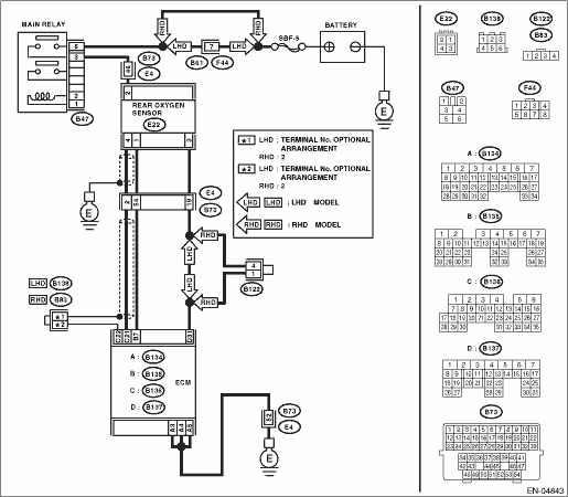
(B134) No. 3 — Chassis ground:
(B134) No. 4 — Chassis ground:
(B134) No. 5 — Chassis ground:
|
Is the resistance less than 5 Ω?
|
|
Repair the harness and connector.
NOTE:
In this case, repair the following item:
• Open circuit of harness between ECM and engine ground cable
• Poor contact in ECM connector
• Poor contact of coupling connector
|
2.CHECK CURRENT DATA.
2) Read the data of rear oxygen sensor heater current using the Subaru Select Monitor or general scan tool.
NOTE:
• Subaru Select Monitor
For detailed operation procedure, refer to “READ CURRENT DATA FOR ENGINE”. 
• General scan tool
For detailed operation procedure, refer to the general scan tool operation manual.
|
Is the current 0.2 A or more?
|
Repair the connector.
NOTE:
In this case, repair the following item:
• Poor contact of the rear oxygen sensor connector
• Poor contact in rear oxygen sensor connecting harness connector
• Poor contact in ECM connector
|
|
3.CHECK OUTPUT SIGNAL OF ECM.
1) Start and idle the engine.
2) Measure the voltage between ECM connector and chassis ground.
Connector & terminal
(B135) No. 7 (+) — Chassis ground (−):
|
Is the voltage less than 1 V?
|
|
|
4.CHECK OUTPUT SIGNAL OF ECM.
Measure the voltage between ECM connector and chassis ground.
Connector & terminal
(B135) No. 7 (+) — Chassis ground (−):
|
Does the voltage change by shaking the harness and connector of ECM while monitoring the value on voltage meter?
|
Repair the poor contact of ECM connector.
|
|
5.CHECK OUTPUT SIGNAL OF ECM.
1) Turn the ignition switch to OFF.
2) Disconnect the connector from the rear oxygen sensor.
3) Measure the voltage between ECM connector and chassis ground.
Connector & terminal
(B135) No. 7 (+) — Chassis ground (−):
|
Is the voltage less than 1 V?
|
Replace the ECM.
|
Repair the short to power supply in the harness between ECM and rear oxygen sensor connector. After repair, replace the ECM.
|
6.CHECK POWER SUPPLY TO REAR OXYGEN SENSOR.
1) Turn the ignition switch to OFF.
2) Disconnect the connector from the rear oxygen sensor.
3) Turn the ignition switch to ON.
4) Measure the voltage between rear oxygen sensor connector and chassis ground.
Connector & terminal
(B73) No. 46 (+) — Chassis ground (−):
|
Is the voltage 10 V or more?
|
|
Repair the power supply circuit.
NOTE:
In this case, repair the following item:
• Open circuit of harness between main relay and rear oxygen sensor connector
• Poor contact of the rear oxygen sensor connector
• Poor contact of coupling connector
|
7.CHECK REAR OXYGEN SENSOR.
1) Turn the ignition switch to OFF.
2) Measure the resistance between the rear oxygen sensor connector terminals.
|
Is the resistance less than 30 Ω?
|
Repair the harness and connector.
NOTE:
In this case, repair the following item:
• Open circuit of harness between the rear oxygen sensor and ECM connector
• Poor contact of the rear oxygen sensor connector
• Poor contact in ECM connector
• Poor contact of coupling connector
|
Replace the rear oxygen sensor.
|