1.CHECK SECONDARY AIR PUMP FUSE.
Check if the secondary air combination valve fuse (10 A) is blown out.
|
|
|
|
2.CHECK HARNESS BETWEEN FUSE BOX AND SECONDARY AIR COMBINATION VALVE.
1) Remove the secondary air combination valve fuse (10 A) from the fuse box.
2) Disconnect connectors from the secondary air combination valves (LH and RH).
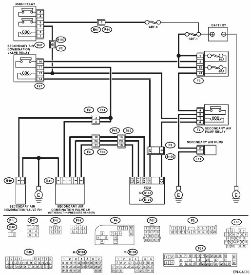
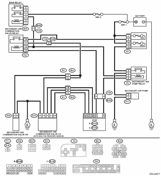
3) Measure the resistance between the secondary air combination valve relay and secondary air combination valve connector terminals, and chassis ground.
Connector & terminal
(F9) No. 2 — Chassis ground:
(E41) No. 6 — Chassis ground:
(E40) No. 2 — Chassis ground:
|
Is the resistance 1 MΩ or more?
|
Replace the fuse with a new part, and then connect the secondary air combination valve connector. 
|
Repair ground short circuit of harness between the fuse box and the secondary air combination valves (LH and RH).
|
3.CHECK SECONDARY AIR COMBINATION VALVE OPERATION.
1) Connect the test mode connector.
2) Turn the ignition switch to ON.
3) Perform operation check for the secondary air combination valve using the Subaru Select Monitor.
NOTE:
Refer to “Compulsory Valve Operation Check Mode” for more operation procedure.
|
Does the secondary air combination valves repeatedly switch to ON and OFF?
|
|
|
4.CHECK DUCT BETWEEN SECONDARY AIR PUMP AND SECONDARY AIR COMBINATION VALVE.
Inspection of the duct between the secondary air pump and secondary air combination valve.
|
Is there damage, clog or disconnection of the duct?
|
Replace, clean or connect the duct.
|
|
5.CHECK PIPE BETWEEN SECONDARY AIR COMBINATION VALVE AND CYLINDER HEAD.
Inspection of the pipe between the secondary air combination valve and cylinder head.
|
Is there damage, clog or disconnection of the pipe?
|
Replace, clean or connect the pipe.
|
Temporary poor contact occurs. Check the poor contact of connector.
|
6.CHECK POWER SUPPLY TO SECONDARY AIR COMBINATION VALVE.
1) Disconnect connectors from the secondary air combination valves (LH and RH).
2) In the condition of step 3, measure the voltage between the secondary air combination valve and the chassis ground.
Connector & terminal
(E41) No. 6 (+) — Chassis ground (−):
(E40) No. 2 (+) — Chassis ground (−):
|
Does the voltage repeatedly change between 10 V and 0 V?
|
Replace the secondary air combination valve.
|
|
7.CHECK HARNESS BETWEEN SECONDARY AIR COMBINATION VALVES AND CHASSIS GROUND.
Measure the resistance between the secondary air combination valve connector terminals and chassis ground.
Connector & terminal
(E41) No. 4 — Chassis ground:
(E40) No. 1 — Chassis ground:
|
Is the resistance less than 1 Ω?
|
|
Repair the open circuit of harness between secondary air combination valves and chassis ground.
|
8.CHECK HARNESS BETWEEN SECONDARY AIR COMBINATION VALVE RELAY AND SECONDARY AIR COMBINATION VALVE CONNECTOR TERMINAL.
1) Turn the ignition switch to OFF.
2) Remove the secondary air pump relay from the relay box.
3) Measure resistance between the secondary air combination valve relay and secondary air combination valve connector.
Connector & terminal
(F27) No. 11 — (E41) No. 6:
(F27) No. 11 — (E40) No. 2:
|
Is the resistance less than 1 Ω?
|
|
Repair the open circuit between the secondary air combination valve relay and secondary air combination valve connector.
|
9.CHECK SECONDARY AIR COMBINATION VALVE RELAY.
1) Turn the ignition switch to OFF.
2) Connect the battery to the secondary air combination valve relay terminals No. 12 and 14.
3) Measure the resistance between the secondary air combination valve relay terminals.
|
Is the resistance less than 1 Ω?
|
|
Replace the secondary air combination valve relay.
|
10.CHECK SECONDARY AIR COMBINATION VALVE RELAY.
Measure the resistance between the secondary air combination valve relay terminals with the battery disconnected.
|
Is the resistance 1 MΩ or more?
|
|
Replace the secondary air combination valve relay.
|
11.CHECK SECONDARY AIR COMBINATION VALVE RELAY POWER SOURCE.
1) Turn the ignition switch to ON.
2) Measure the voltage between the secondary air combination valve relay connector and chassis ground.
Connector & terminal
(F27) No. 10 (+) — Chassis ground (−):
(F27) No. 12 (+) — Chassis ground (−):
|
Is the voltage 10 V or more?
|
|
Repair the open or ground short circuit of power supply circuit.
|
12.CHECK HARNESS BETWEEN ECM AND SECONDARY AIR COMBINATION VALVE RELAY CONNECTOR.
1) Turn the ignition switch to OFF.
2) Disconnect the connector of ECM.
3) Measure the resistance of the harness between the ECM and secondary air combination valve relay connector.
Connector & terminal
(B136) No. 30 — (F27) No. 14:
|
Is the resistance less than 1 Ω?
|
|
Repair open circuit of the harness between the ECM and secondary air pump relay connector.
|
13.CHECK HARNESS BETWEEN ECM AND SECONDARY AIR COMBINATION VALVE RELAY CONNECTOR.
Connector & terminal
(F27) No. 14 — Chassis ground:
|
Is the resistance 1 MΩ or more?
|
Replace the ECM.
|
Repair ground short circuit of the harness between the ECM and secondary air pump relay connector.
|