1.CHECK ANY OTHER DTC ON DISPLAY.
Check for the following DTC.
P0413, P0414,P0418, P1410, P1418, P2432 or P2433
|
Is any of the DTCs displayed?
|
Check the appropriate DTC using the “List of Diagnostic Trouble Code (DTC)”. 
|
|
2.CHECK SECONDARY AIR PUMP FUSE.
Check if the secondary air pump fuse (60 A) is blown out.
|
|
|
|
3.CHECK HARNESS BETWEEN FUSE BOX AND SECONDARY AIR PUMP.
1) Remove the secondary air pump fuse from the fuse box.
2) Disconnect the secondary air pump connector.
3) Measure resistance between the secondary air pump fuse and secondary air pump connector terminal, and chassis ground.
Connector & terminal
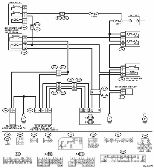
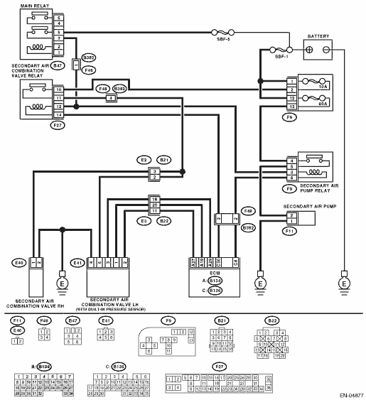
(F9) No. 13 — Chassis ground:
(F11) No. 2 — Chassis ground:
|
Is the resistance 1 MΩ or more?
|
Replace the fuse with a new part, and then connect the secondary air pump connector.
|
Repair ground short of the harness between the fuse box and the secondary air pump.
|
4.CHECK SECONDARY AIR PUMP OPERATION.
1) Connect the test mode connector.
2) Turn the ignition switch to ON.
3) Perform the Clear Memory Mode.
4) Perform operation check for the secondary air pump using the Subaru Select Monitor.
NOTE:
• Refer to “Compulsory Valve Operation Check Mode” for more operation procedure.
• The compulsory operation using the Subaru Select Monitor is performed only for 10 seconds in order to protect the secondary air pump. When operating again, perform the Clear Memory Mode.
|
Does the secondary air pump operate?
|
|
|
5.CHECK DUCT BETWEEN SECONDARY AIR PUMP AND COMBINATION VALVE.
Inspection of the duct between the secondary air pump and combination valve.
|
Is there damage, clog or disconnection of the duct?
|
Replace or connect the duct.
|
Replace the secondary air combination valve (LH).
NOTE:
The secondary air pressure sensor is a built-in part of the secondary air combination valve (LH).
|
6.CHECK POWER SUPPLY TO SECONDARY AIR PUMP.
1) Remove the battery negative terminal, and reconnect.
2) Disconnect the secondary air pump connector.
3) In the condition of step 4, measure the voltage between the secondary air pump and the chassis ground.
Connector & terminal
(F11) No. 2 (+) — Chassis ground (−):
|
Is the voltage 10 V or more?
|
Replace the secondary air pump.
|
|
7.CHECK HARNESS BETWEEN SECONDARY AIR PUMP RELAY AND SECONDARY AIR PUMP CONNECTOR.
1) Turn the ignition switch to OFF.
2) Remove the secondary air pump relay from the relay box.
3) Measure resistance between the secondary air pump relay and secondary air pump connector terminal
Connector & terminal
(F9) No. 5 — (F11) No. 2:
|
Is the resistance less than 1 Ω?
|
|
Repair the open circuit between secondary air pump relay and secondary air pump connector terminal.
|
8.CHECK HARNESS BETWEEN SECONDARY AIR PUMP CONNECTOR AND CHASSIS GROUND.
Measure the resistance of the harness between secondary air pump connector and chassis ground.
Connector & terminal
(F11) No. 1 — Chassis ground:
|
Is the resistance less than 1 Ω?
|
|
Repair the open circuit of the harness between secondary air pump connector and chassis ground.
|
9.CHECK SECONDARY AIR PUMP RELAY.
1) Turn the ignition switch to OFF.
2) Connect the battery to the secondary air pump relay terminals No. 3 and 6.
3) Measure the resistance between secondary air pump relay terminals.
|
Is the resistance less than 1 Ω?
|
|
Replace the secondary air pump relay.
|
10.CHECK SECONDARY AIR PUMP RELAY POWER SOURCE.
1) Turn the ignition switch to ON.
2) Measure the voltage between the secondary air pump relay connector and chassis ground.
Connector & terminal
(F9) No. 3 (+) — Chassis ground (−):
(F9) No. 4 (+) — Chassis ground (−):
|
Is the voltage 10 V or more?
|
|
Repair the open or ground short circuit of power supply circuit.
|
11.CHECK HARNESS BETWEEN ECM AND SECONDARY AIR PUMP RELAY CONNECTOR.
1) Turn the ignition switch to OFF.
2) Disconnect the connector of ECM.
3) Measure the resistance of the harness between the ECM and secondary air pump relay connector terminal.
Connector & terminal
(B136) No. 8 — (F9) No. 6:
|
Is the resistance less than 1 Ω?
|
Replace the ECM.
|
Repair open circuit of the harness between the ECM and secondary air pump relay connector terminal.
|