1.CHECK CURRENT DATA.
2) Read the data of tumble generator valve position sensor signal using Subaru Select Monitor or general scan tool.
NOTE:
• Subaru Select Monitor
For detailed operation procedure, refer to “READ CURRENT DATA FOR ENGINE”. 
• General scan tool
For detailed operation procedure, refer to the general scan tool operation manual.
|
Is the voltage less than 0.1 V?
|
|
Even if the malfunction indicator light illuminates, the circuit has returned to a normal condition at this time. Temporary poor contact of connector may be the cause.
NOTE:
In this case, repair the following item:
• Poor contact of tumble generator valve position sensor connector
• Poor contact in ECM connector
• Poor contact of coupling connector
|
2.CHECK INPUT SIGNAL OF ECM.
Measure the voltage between ECM connector and chassis ground.
Connector & terminal
(B134) No. 19 (+) — Chassis ground (−):
|
Is the voltage 4.5 V or more?
|
|
|
3.CHECK INPUT SIGNAL OF ECM.
Measure the voltage between ECM connector and chassis ground.
Connector & terminal
(B134) No. 19 (+) — Chassis ground (−):
|
Does the voltage change by shaking the harness and connector of ECM while monitoring the value on voltage meter?
|
Repair the poor contact of ECM connector.
|
Contact with SUBARU distributor service.
|
4.CHECK INPUT SIGNAL OF ECM.
Measure the voltage between ECM connector and chassis ground.
Connector & terminal
(B134) No. 16 (+) — Chassis ground (−):
|
Is the voltage less than 0.1 V?
|
|
|
5.CHECK INPUT SIGNAL FOR ECM (USING SUBARU SELECT MONITOR).
Measure the voltage between ECM connector and chassis ground.
|
Does the voltage change by shaking the harness and connector of ECM while monitoring the value with Subaru Select Monitor?
|
Repair the poor contact of ECM connector.
|
|
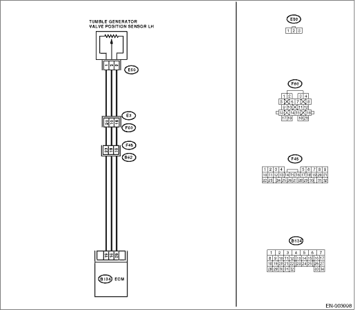
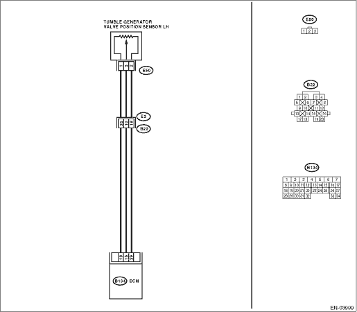
6.CHECK HARNESS BETWEEN ECM AND TUMBLE GENERATOR VALVE POSITION SENSOR CONNECTOR.
1) Turn the ignition switch to OFF.
2) Disconnect the connector from tumble generator valve position sensor.
3) Turn the ignition switch to ON.
4) Measure the voltage between tumble generator valve position sensor connector and engine ground.
Connector & terminal
(E50) No. 1 (+) — Engine ground (−):
|
Is the voltage 4.5 V or more?
|
|
Repair the harness and connector.
NOTE:
In this case, repair the following item:
• Open circuit of harness between tumble generator valve position sensor and ECM connector
• Poor contact of tumble generator valve position sensor connector
• Poor contact in ECM connector
• Poor contact of coupling connector
|
7.CHECK HARNESS BETWEEN ECM AND TUMBLE GENERATOR VALVE POSITION SENSOR CONNECTOR.
1) Turn the ignition switch to OFF.
2) Measure the resistance of harness between ECM connector and tumble generator valve position sensor connector.
Connector & terminal
(B134) No. 16 — (E50) No. 3:
|
Is the resistance less than 1 Ω?
|
|
Repair the harness and connector.
NOTE:
In this case, repair the following item:
• Open circuit of harness between tumble generator valve position sensor and ECM connector
• Poor contact in ECM connector
• Poor contact of tumble generator valve position sensor connector
• Poor contact of coupling connector
|
8.CHECK HARNESS BETWEEN ECM AND TUMBLE GENERATOR VALVE POSITION SENSOR CONNECTOR.
Measure the resistance of harness between tumble generator valve position sensor connector and engine ground.
Connector & terminal
(E50) No. 3 — Engine ground:
|
Is the resistance 1 MΩ or more?
|
|
Repair the ground short circuit of harness between tumble generator valve position sensor and ECM connector.
|
9.CHECK POOR CONTACT.
Check for poor contact in the tumble generator valve position sensor connector.
|
Is there poor contact in the tumble generator valve position sensor connector?
|
Repair the poor contact of tumble generator valve position sensor connector.
|
Replace the tumble generator valve position sensor.
|