|
|
|
|
|
|
|
When the fuse is inserted to FWD switch, does the LED illuminate?
|
Go to step check cruise control switch.
|
|
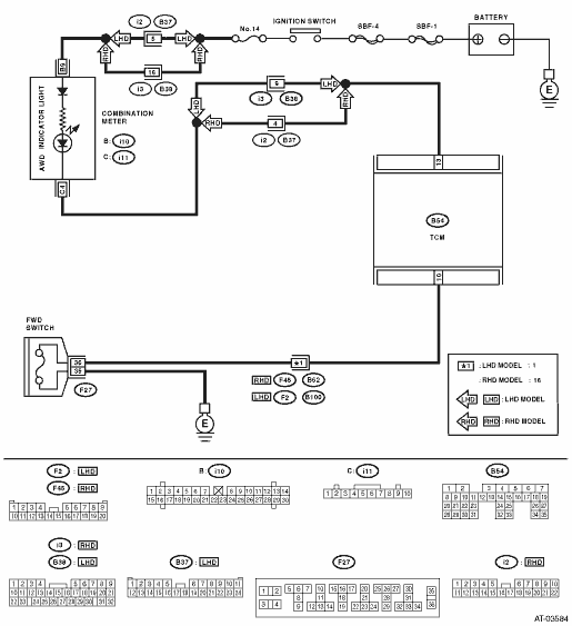
3.CHECK HARNESS CONNECTOR BETWEEN TCM AND FWD SWITCH.
1) Turn the ignition switch to OFF.
2) Disconnect the connector from the TCM and FWD switches.
3) Measure the resistance of harness between TCM and FWD switch connector.
Connector & terminal
(B54) No. 10 — (F27) No. 36:
|
Is the resistance less than 1 Ω?
|
|
Repair the open circuit of harness between TCM and FWD switch connectors.
|
4.CHECK HARNESS CONNECTOR BETWEEN TCM AND FWD SWITCH.
Measure the resistance of harness connector between TCM and body to make sure that circuit does not short.
Connector & terminal
(B54) No. 10 — Chassis ground:
|
Is the resistance 1 MΩ or more?
|
|
Repair the short circuit of harness between TCM and FWD switch connectors.
|
5.CHECK HARNESS CONNECTOR BETWEEN FWD SWITCH AND CHASSIS GROUND.
Measure the resistance of harness between FWD switch and chassis ground.
Connector & terminal
(F27) No. 35 — Chassis ground:
|
Is the resistance less than 1 Ω?
|
|
Repair the open circuit of harness between FWD switch connector and chassis ground.
|
6.CHECK INPUT SIGNAL FOR TCM.
1) Turn the ignition switch to OFF.
2) Connect the connector to TCM and FWD switch.
3) Turn the ignition switch to ON.
4) Measure the signal voltage for TCM while installing the fuse to FWD switch connector.
Connector & terminal
(B54) No. 10 (+) — Chassis ground (−):
|
Is the voltage less than 1 V?
|
|
|
7.CHECK INPUT SIGNAL FOR TCM.
Measure the signal voltage for TCM with the fuse removed from FWD switch connector.
Connector & terminal
(B54) No. 10 (+) — Chassis ground (−):
|
Is the voltage 10.5 V or more?
|
|
Replace the TCM. 
|
8.CHECK HARNESS CONNECTOR BETWEEN TCM AND COMBINATION METER.
1) Turn the ignition switch to OFF.
2) Disconnect the connectors from TCM and combination meter.
3) Measure the resistance of harness between TCM and diagnosis connector.
Connector & terminal
(B54) No. 13 — (i11) No. 4:
|
Is the resistance less than 1 Ω?
|
|
Repair the open circuit of harness between TCM and combination meter, and the poor contact of the connector.
|
9.CHECK HARNESS CONNECTOR BETWEEN TCM AND COMBINATION METER.
Measure the resistance of the harness connector between TCM and chassis ground to make sure that circuit is not shorted.
Connector & terminal
(B54) No. 13 — Chassis ground:
|
Is the resistance 1 MΩ or more?
|
|
Repair short circuit of harness between TCM and combination meter connector.
|
10.CHECK OUTPUT SIGNAL OF TCM.
1) Turn the ignition switch to OFF.
2) Connect the connector to TCM and combination meter.
3) Turn the ignition switch to ON.
4) Measure the signal voltage for TCM while installing and removing the fuse to FWD switch connector.
Connector & terminal
(B54) No. 13 (+) — Chassis ground (−):
|
Is the voltage less than 1 V?
|
|
|
11.CHECK OUTPUT SIGNAL OF TCM.
Measure the signal voltage for TCM with the fuse removed from FWD switch connector.
Connector & terminal
(B54) No. 13 (+) — Chassis ground (−):
|
Is the voltage 10.5 V or more?
|
|
Replace the TCM.
|
|
|
Is there poor contact in FWD switch circuit?
|
|
Replace the TCM.
|