1.CHECK INSTALLATION OF TCM CONNECTOR.
Turn the ignition switch to OFF.
|
Is the TCM connector connected correctly?
|
|
Connect the TCM connector securely.
|
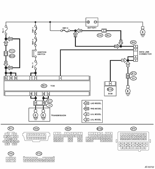
2.CHECK SUBARU SELECT MONITOR POWER SUPPLY CIRCUIT.
Measure the voltage between data link connector and chassis ground.
Connector & terminal
(B40) No. 1 (+) — Chassis ground (−):
|
Is the voltage 10 V or more?
|
|
Repair harness connector between the battery and data link connector, and poor contact of the connector.
|
3.CHECK SUBARU SELECT MONITOR GROUND CIRCUIT.
1) Disconnect the connectors from the ECM. (2.5 L model)
2) Measure the resistance of harness between the data link connector and ECM or the chassis ground.
Connector & terminal
2.0 L model
(B40) No. 12 — Chassis ground:
(B40) No. 13 — Chassis ground:
2.5 L model
(B40) No. 12 — (B134) No. 6:
(B40) No. 12 — (B134) No. 6:
|
Is the resistance less than 1 Ω?
|
|
Repair the open circuit of harness between data link connector and chassis ground or ECM, and poor contact of connector.
|
4.CHECK ENGINE GROUND CIRCUIT.
Check the engine ground circuit.
|
Is the engine ground circuit normal?
|
|
Repair ground circuit of ECM.
|
5.CHECK COMMUNICATION OF SUBARU SELECT MONITOR.
1) Turn the ignition switch to ON.
2) Using the Subaru Select Monitor, check whether communication to the transmission system can be executed normally.
|
Is the name of system displayed on Subaru Select Monitor?
|
|
|
6.CHECK COMMUNICATION OF SUBARU SELECT MONITOR.
1) Turn the ignition switch to OFF.
2) Disconnect the TCM connector.
3) Check whether communication to the engine system, ABS and airbag system can be executed normally.
|
Is the name of system displayed on Subaru Select Monitor?
|
|
|
7.CHECK COMMUNICATION OF SUBARU SELECT MONITOR.
1) Turn the ignition switch to OFF.
2) Connect the TCM connector.
3) Disconnect the ABS, VDC and airbag connector.
CAUTION:
Observe the safety precautions before disconnecting the airbag connectors. 
4) Check whether communication to transmission system can be executed normally.
|
Is the name of system displayed on Subaru Select Monitor?
|
Inspect the ABS, VDC and airbag module.
|
|
8.CHECK HARNESS CONNECTOR BETWEEN EACH CONTROL MODULE AND DATA LINK CONNECTOR.
1) Turn the ignition switch to OFF.
2) Disconnect the following TCM connectors.
3) Check whether communication to ECM can be executed normally.
|
Is the name of system displayed on Subaru Select Monitor?
|
|
|
9.CHECK HARNESS CONNECTOR BETWEEN EACH CONTROL MODULE AND DATA LINK CONNECTOR.
1) Turn the ignition switch to OFF.
2) Disconnect the connector of ECM.
3) Measure the resistance between data link connector and chassis ground.
Connector & terminal
(B40) No. 10 — Chassis ground:
|
Is the resistance 1 MΩ or more?
|
|
Check harness and connector between each control module and data link connector.
|
10.CHECK OUTPUT SIGNAL OF TCM.
1) Turn the ignition switch to ON.
2) Measure the voltage between data link connector and chassis ground.
Connector & terminal
(B40) No. 10 (+) — Chassis ground (−):
|
Is the voltage 1 V or more?
|
Check harness and connector between each control module and data link connector.
|
|
11.CHECK HARNESS CONNECTOR BETWEEN TCM AND DATA LINK CONNECTOR.
Measure the resistance between TCM connector and data link connector.
Connector & terminal
(B54) No. 8 — (B40) No. 10:
|
Is the resistance less than 1 Ω?
|
|
Repair the harness and connector between TCM and data link connector.
|
12.CHECK FOR IMPROPER CONNECTION OF TRANSMISSION HARNESS CONNECTOR.
|
Is the transmission harness connector connected to bulkhead harness connector correctly?
|
|
Connect the bulkhead harness connector to transmission harness connector.
|
13.CHECK POOR CONTACT OF CONNECTORS.
|
Is there poor contact in control module power supply and data link connector?
|
|
|
14.CHECK POWER SUPPLY OF TCM.
1) Disconnect the connector from TCM.
2) Measure the voltage between TCM connector and chassis ground.
Connector & terminal
(B54) No. 25 (+) — Chassis ground (−):
(B54) No. 26 (+) — Chassis ground (−):
(B54) No. 27 (+) — Chassis ground (−):
|
Is the voltage 10 — 13 V?
|
|
|
15.CHECK FUSE (NO. 4).
Remove the fuse (No. 4).
|
Is the fuse (No. 4) blown out?
|
Replace the fuse (No. 4). If the replaced fuse (No. 4) has blown out easily, repair the short circuit of harness between fuse (No. 4) and TCM.
|
Repair the open circuit of harness between fuse (No. 4) and TCM, or fuse (No. 4) and battery, and poor contact of the connector.
|
16.CHECK IGNITION POWER SUPPLY CIRCUIT.
1) Turn the ignition switch to ON (engine OFF).
2) Measure the ignition power supply voltage between TCM connector and chassis ground.
Connector & terminal
(B54) No. 1 (+) — Chassis ground (−):
(B54) No. 2 (+) — Chassis ground (−):
|
Is the voltage 10 — 13 V?
|
|
|
17.CHECK FUSE (NO. 12).
Remove the fuse (No. 11).
|
Is the fuse (No. 11) blown out?
|
Replace the fuse (No. 11). If the replaced fuse (No. 11) has blown out easily, repair the short circuit of harness between fuse (No. 11) and TCM.
|
Repair the open circuit of harness between fuse (No. 11) and TCM, or fuse (No. 11) and battery, and poor contact of the connector.
|
18.CHECK HARNESS CONNECTOR BETWEEN TCM AND TRANSMISSION.
1) Turn the ignition switch to OFF.
2) Disconnect the connectors from TCM and transmission.
3) Measure the resistance of harness between TCM and transmission connector.
Connector & terminal
(B54) No. 22 — (B11) No. 19:
(B54) No. 23 — (B11) No. 19:
(B54) No. 20 — (B11) No. 20:
(B54) No. 21 — (B11) No. 20:
|
Is the resistance less than 1 Ω?
|
|
Repair the open circuit of harness between TCM and transmission harness connector, and poor contact of connector.
|
19.CHECK HARNESS CONNECTOR BETWEEN TRANSMISSION AND TRANSMISSION GROUND.
Measure the resistance of the harness between transmission and transmission ground.
Connector & terminal
(T4) No. 19 — Transmission ground:
(T4) No. 20 — Transmission ground:
|
Is the resistance less than 1 Ω?
|
|
Repair the open circuit of the harness between transmission and transmission ground.
|
20.CHECK POOR CONTACT OF CONNECTORS.
|
Is there poor contact in TCM power supply, ground and data link connector?
|
|
Replace the TCM.
|