DTC DETECTING CONDITION:
Shift lock solenoid malfunction, open or short reverse inhibitor control circuit
TROUBLE SYMPTOM:
• Gear is shifted from “N” range to “P” range during driving at 20 km/h (12 MPH) or more.
• Gear cannot be selected from “N” range to “R” range.
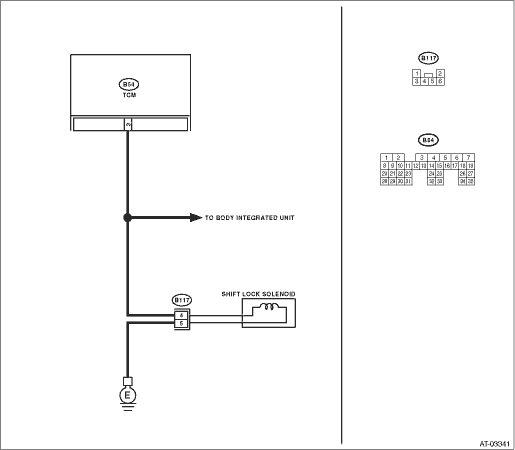
WIRING DIAGRAM:

| STEP | CHECK | YES | NO |
|
Is the resistance less than 1 Ω? |
|
Repair the open circuit of harness between TCM and shift lock solenoid connector. |
|
|
Is the resistance 1 MΩ or more? |
|
Repair the short circuit of harness between TCM and shift lock solenoid connector. |
|
|
Is the resistance less than 1 Ω? |
|
Repair the open circuit of harness between chassis ground and shift lock solenoid connector. |
|
|
Is the resistance between 20 — 40 Ω? |
|
Replace the shift lock solenoid. |
|
|
Is the voltage 10.5 V or more? |
|
|
|
|
1) Lift up the vehicle and place it on rigid racks. NOTE: Raise all wheels off the floor. 2) Start the engine. 3) Shift the select lever to “D” range and slowly increase vehicle speed to exceed 20 km/h (12 MPH). NOTE: The speed difference between front and rear wheels may illuminate the ABS warning light, but this does not indicate a malfunction. When AT control diagnosis is finished, perform the ABS or VDC clear memory of on-board diagnostics system. 4) Measure the voltage between TCM and chassis ground. Connector & terminal (B54) No. 3 (+) — Chassis ground (−): |
Is the voltage less than 1 V? |
Even if the power indicator light is blinking, the circuit is in normal condition at this time. A temporary poor contact of connector or harness may be the cause. Repair the harness or connector in the reverse inhibitor control circuit. |
|
|
Is there poor contact in the reverse control circuit? |
Repair the poor contact. |
Replace the TCM. |
