1.CHECK HARNESS CONNECTOR BETWEEN TCM AND TRANSMISSION.
1) Turn the ignition switch to OFF.
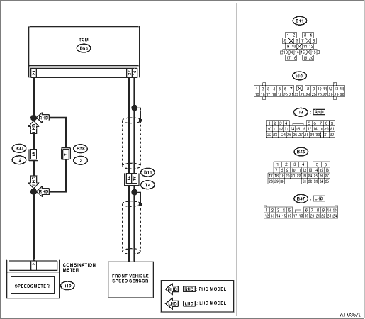
2) Disconnect the connectors from TCM and transmission.
3) Measure the resistance of harness between TCM connector and transmission connector.
Connector & terminal
(B55) No. 27 — (B11) No. 14:
|
Is the resistance less than 1 Ω?
|
|
Repair the open circuit of harness between TCM and transmission connector.
|
2.CHECK HARNESS CONNECTOR BETWEEN TCM AND TRANSMISSION.
Measure the resistance of harness between TCM connector and transmission connector.
Connector & terminal
(B55) No. 16 — (B11) No. 18:
|
Is the resistance less than 1 Ω?
|
|
Repair the open circuit of harness between TCM and transmission connector, and poor contact of the connector.
|
3.CHECK HARNESS CONNECTOR BETWEEN TCM AND TRANSMISSION.
Measure the resistance of harness between TCM connector and transmission connector.
Connector & terminal
(B55) No. 27 — Chassis ground:
|
Is the resistance 1 MΩ or more?
|
|
Repair the short circuit of harness between TCM and transmission connector.
|
4.CHECK HARNESS CONNECTOR BETWEEN TCM AND TRANSMISSION.
Measure the resistance of harness between TCM connector and transmission connector.
Connector & terminal
(B55) No. 16 — Chassis ground:
|
Is the resistance 1 MΩ or more?
|
|
Repair the short circuit of the harness between TCM and transmission connector, and poor contact of connector.
|
5.CHECK FRONT VEHICLE SPEED SENSOR.
Measure the resistance between transmission connector receptacle’s terminals.
|
Is the resistance between 450 — 650 Ω?
|
|
Replace the front vehicle speed sensor. 
|
6.CHECK INPUT SIGNAL FOR TCM USING SUBARU SELECT MONITOR.
1) Connect all connectors.
2) Connect the Subaru Select Monitor to the data link connector.
3) Lift up the vehicle and place it on rigid racks.
NOTE:
Raise all wheels off the floor.
4) Turn the ignition switch to ON, and the Subaru Select Monitor power switch to ON.
6) Read the data of vehicle speed using Subaru Select Monitor.
• Compare the speedometer with Subaru Select Monitor indications.
• Vehicle speed is indicated in “km/h” or “MPH”
7) Slowly increase the vehicle speed to 60 km/h or 37 MPH.
NOTE:
The speed difference between front and rear wheels may illuminate the ABS warning light, but this does not indicate a malfunction. When AT control diagnosis is finished, perform the ABS memory clearance procedure of on-board diagnostics system.
|
Does the speedometer indication increase as the Subaru Select Monitor front wheel speed data increases?
|
Even if the power indicator light is blinking, the circuit is in normal condition at this time. A temporary poor contact of connector or harness may be the cause. Repair the harness in of front vehicle speed sensor circuit.
|
|
|
|
Is there poor contact in front vehicle speed sensor circuit?
|
|
Replace the TCM.
|