IMMOBILIZER (DIAGNOSTICS) > Diagnostics Chart for Immobilizer Indicator Light

INSPECTION

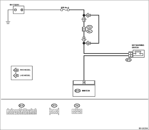
1. CHECK IMMOBILIZER INDICATOR CIRCUIT
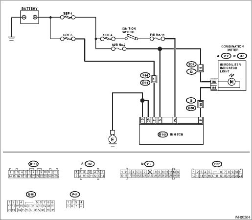
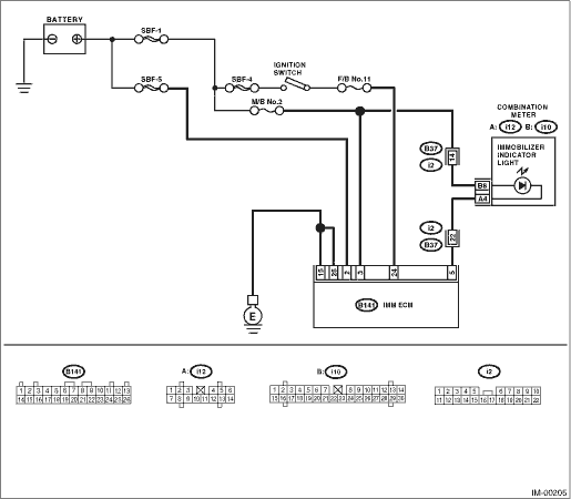
WIRING DIAGRAM:

LHD model

RHD model

STEPCHECKYESNO

1.CHECK IMMOBILIZER INDICATOR LIGHT.

1) Turn the ignition switch to OFF.

2) Disconnect the harness connector from IMM ECM.

3) Connect a resistor (100 Ω) between IMM ECM harness connector terminal No. 5 and chassis ground.

Does the security indicator light illuminate?

2.CHECK IMM ECM GROUND CIRCUIT.

Measure the resistance between IMM ECM harness connector terminal and chassis ground.

Connector & terminal

(B141) No. 15 — Chassis ground:

(B141) No. 25 — Chassis ground:

Is the resistance less than 10 Ω?

Repair the open circuit of IMMCM ground circuit.

3.CHECK IMM ECM IGNITION CIRCUIT.

1) Turn the ignition switch to ON. (engine OFF)

2) Measure the voltage between IMM ECM harness connector terminal and chassis ground.

Connector & terminal

(B141) No. 24 (+) — Chassis ground (−):

Is the voltage 10 V or more?

Check the harness for open or short between IMM ECM and ignition switch.

4.CHECK IMM ECM POWER SUPPLY CIRCUIT.

1) Turn the ignition switch to OFF.

2) Measure the voltage between IMM ECM harness connector terminal and chassis ground.

Connector & terminal

(B141) No. 3 (+) — Chassis ground (−):

Is the voltage 10 V or more?

Replace the IMM ECM and then replace all ignition keys (including the transponder). Execute the registration procedure next. Refer to “REGISTRATION MANUAL FOR IMMOBILIZER (Pub. No. S0820GZ)”.

Check the harness for open or short between IMM ECM and fuse.

5.CHECK COMBINATION METER CIRCUIT.

1) Remove the combination meter.

2) Measure the voltage between combination meter harness connector terminal and chassis ground.

Connector & terminal

(i10) No. 8 (+) — Chassis ground (−):

Is the voltage 10 V or more?

Check the harness for open or short between combination meter and fuse.

6.CHECK COMBINATION METER CIRCUIT.

Measure the resistance between IMM ECM harness connector terminal and the combination meter harness connector terminal.

Connector & terminal

(B141) No. 5 — (i12) No. 4:

Is the resistance less than 10 Ω?

Faulty LED. Replace the combination meter print circuit.

Repair the harness or connector.

2. CHECK KEY SWITCH CIRCUIT

WIRING DIAGRAM:

STEPCHECKYESNO

1.CHECK POWER SUPPLY CIRCUIT.

1) Disconnect the harness connector from key warning switch.

2) Measure the voltage between key warning switch harness connector terminal and chassis ground.

Connector & terminal

(B74) No. 1 (+) — Chassis ground (−):

Is the voltage 10 V or more?

Check the harness for an open or short between the key warning switch and fuse.

2.CHECK KEY WARNING SWITCH.

1) Insert the ignition key into the ignition switch. (OFF or ACC position)

2) Measure the resistance between key warning switch connector terminals.

Terminals

No. 1 — No. 2:

Is the resistance less than 1 Ω?

Replace the key warning switch.

3.CHECK KEY WARNING SWITCH.

1) Remove the ignition key from the ignition switch.

2) Measure the resistance between key warning switch connector terminals.

Terminals

No. 1 — No. 2:

Is the resistance 1 MΩ or more?

Replace the key warning switch.

4.CHECK HARNESS BETWEEN KEY WARNING SWITCH AND IMM ECM.

1) Disconnect the harness connector from key warning switch.

2) Disconnect the harness connector from IMM ECM.

3) Measure the resistance between key warning switch harness connector terminal and IMM ECM harness connector terminal.

Connector & terminal

(B74) No. 2 — (B141) No. 26:

Is the resistance less than 10 Ω?

Replace the IMM ECM and then replace all ignition keys (including the transponder). Execute the registration procedure next. Refer to “REGISTRATION MANUAL FOR IMMOBILIZER (Pub. No. S0820GZ)”.

Repair the harness between key warning switch and IMM ECM.