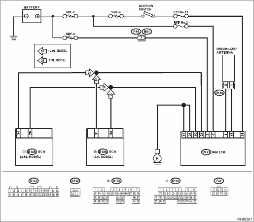
1.CHECK IMM ECM POWER SUPPLY CIRCUIT.
1) Turn the ignition switch to OFF.
2) Disconnect the harness connector from IMM ECM.
3) Measure the voltage between IMM ECM harness connector terminal and chassis ground.
Connector & terminal
(B141) No. 2 (+) — Chassis ground (−):
(B141) No. 3 (+) — Chassis ground (−):
|
Is the voltage 10 V or more?
|
|
Check the harness for open or short between IMM ECM and fuse.
|
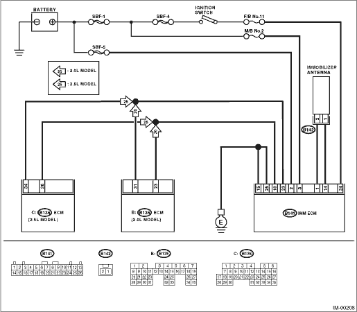
2.CHECK IGNITION SWITCH CIRCUIT.
1) Turn the ignition switch to ON. (engine OFF)
2) Measure the voltage between IMM ECM harness connector terminal and chassis ground.
Connector & terminal
(B141) No. 24 (+) — Chassis ground (−):
|
Is the voltage 10 V or more?
|
|
Check the harness for open or short between IMM ECM and ignition switch.
|
3.CHECK IMM ECM GROUND CIRCUIT.
1) Turn the ignition switch to OFF.
2) Measure the resistance between IMM ECM harness connector terminal and chassis ground.
Connector & terminal
(B141) No. 15 — Chassis ground:
(B141) No. 25 — Chassis ground:
|
Is the resistance less than 10 Ω?
|
|
Repair the open circuit of IMMCM ground circuit.
|
4.CHECK HARNESS BETWEEN IMM ECM AND ECM.
1) Disconnect the harness connector from the ECM and IMM ECM.
2) Measure the resistance between IMM ECM harness connector terminal and ECM harness connector terminal.
Connector & terminal
2.0 L model
(B141) No. 10 — (B135) No. 23
2.5 L model
(B141) No. 10 — (B136) No. 26
|
Is the resistance less than 10 Ω?
|
|
Repair the open circuit of harness between IMM ECM and ECM.
|
5.CHECK HARNESS BETWEEN IMM ECM AND ECM.
Measure the resistance between IMM ECM harness connector terminal and ECM harness connector terminal.
Connector & terminal
2.0 L model
(B141) No. 23 — (B135) No. 31
2.5 L model
(B141) No. 23 — (B136) No. 34
|
Is the resistance less than 10 Ω?
|
|
Repair the open circuit of harness between IMM ECM and ECM.
|
6.CHECK HARNESS OF COMMUNICATION LINE.
1) Turn the ignition switch to ON. (engine OFF)
2) Measure the voltage between IMM ECM harness connector terminal and chassis ground.
Connector & terminal
(B141) No. 10 (+) — Chassis ground (−):
(B141) No. 23 (+) — Chassis ground (−):
|
|
|
There is a short circuit in the battery voltage circuit or ignition switch “ON” circuit. Repair the harness between IMM ECM and ECM.
|
7.CHECK HARNESS OF COMMUNICATION LINE.
Measure voltage between the ECM harness connector terminal and engine ground.
Connector & terminal
2.0 L model
(B135) No. 23 (+) — Chassis ground (−):
(B135) No. 31 (+) — Chassis ground (−):
2.5 L model
(B136) No. 34 (+) — Chassis ground (−):
(B136) No. 26 (+) — Chassis ground (−):
|
|
|
There is a short circuit in the battery voltage circuit or ignition switch “ON” circuit. Repair the harness between IMM ECM and ECM.
|
8.CHECK ECM BY COMMUNICATION LINE CHECK.
1) Connect the harness connector to ECM.
2) Disconnect the harness connector from IMM ECM.
3) Perform communication line check. 
|
Does “Communication Line not Shorted” appear on the screen?
|
Replace the IMM ECM and then replace all ignition keys (including the transponder). Execute the registration procedure next. Refer to REGISTRATION MANUAL FOR IMMOBILIZER (Pub. No. S0820GZ).
|
Replace the ECM. Perform the registration procedure next. Refer to REGISTRATION MANUAL FOR IMMOBILIZER (Pub. No. S0820GZ).
|