DETECTING CONDITION:
• Brake warning light circuit is shorted.
• Defective sensor/connector
TROUBLE SYMPTOM:
After starting the engine, the brake warning light remains lit though the parking lever is released.
NOTE:
If the ABS warning light is lit, perform the diagnosis of “ABS WARNING LIGHT DOES NOT GO OFF”, then the diagnosis of “BRAKE WARNING LIGHT DOES NOT GO OFF” after repairing it. 
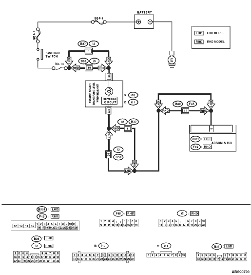
WIRING DIAGRAM:

| STEP | CHECK | YES | NO |
|
Is the connector firmly inserted? |
|
Insert the ABSCM&H/U connector until the clamp locks completely. |
|
|
Is DTC displayed? |
Perform the diagnosis according to DTC. |
|
|
|
Is the amount of brake fluid between the lines of “MAX” and “MIN”? |
|
Replenish brake fluid to the specified value. |
|
|
Is the resistance more than 1 MΩ? |
|
Replace the master cylinder. |
|
|
Is the resistance more than 1 MΩ? |
|
Replace the parking brake switch. |
|
|
Is the resistance more than 1 MΩ? |
|
Repair the harness connector between combination meter and parking brake switch. |
|
|
1) Disconnect the connector (F49) from the ABSCM&H/U. 2) Disconnect the connector (i11) from combination meter. 3) Measure the resistance between the ABSCM&H/U connector and combination meter connector. Connector & terminal LHD model (B301) No. 8 — (i11) No. 3: RHD model (F49) No. 8 — (i11) No. 3: |
Is the resistance less than 0.5 Ω? |
|
Repair the harness between the ABSCM&H/U and the combination meter. |
|
Is there poor contact? |
Repair the connector. |
|
|
|
Is the resistance less than 0.5 Ω? |
Check the combination meter. |
Replace the ABSCM only. |