|
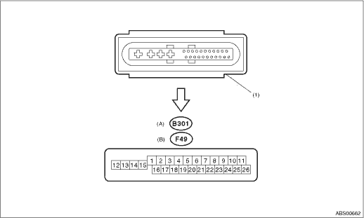
(A) |
LHD model |
(B) |
RHD model |
||
|
(1) |
ABS control module and hydraulic control unit (ABSCM&H/U) connector |
NOTE:
• Terminal numbers in ABSCM&H/U connector are shown in the figure.
• ABS warning light illuminates when the connector is removed from ABSCM&H/U.
|
Description |
Terminal No. (+) — (−) |
Input/Output signal | |
|
ABS wheel speed sensor (Wheel speed sensor) |
Front LH wheel |
1 — 16 |
0.12 — 1 V (at 20 Hz) |
|
Front RH wheel |
6 — 5 | ||
|
Rear LH wheel |
3 — 2 | ||
|
Rear RH wheel |
19 — 4 | ||
|
CAN communication circuit (+) (for AT models only) |
26 |
1.5 — 2.5 V pulse signal | |
|
CAN communication circuit (−) (for AT models only) |
11 |
2.5 — 3.5 V pulse signal | |
|
Valve relay power supply *1 |
14 — 15 |
10 — 15 V | |
|
Motor relay power supply *1 |
13 — 15 |
10 — 15 V | |
|
G sensor |
Power supply |
24 — 10 |
4.75 — 5.25 V |
|
Ground |
10 |
— | |
|
Output |
21 — 10 |
2.1 — 2.5 V when the vehicle is on level surface | |
|
Stop light switch *1 |
20 — 15 |
1.5 V or less when the stop light is OFF; otherwise, 10 — 15 V when the stop light is ON. | |
|
ABS warning light |
22 — 15 |
After turning the ignition switch to ON, 10 — 15 V during 1.5 seconds and 1.5 V or less after 1.5 seconds passed. | |
|
Brake warning light (EBD warning light) |
8 — 15 |
After turning the ignition switch to ON, 10 — 15 V during 1.5 seconds and 1.5 V or less after 1.5 seconds passed. | |
|
Subaru Select Monitor |
7 — 15 |
1.5 V or less when no data is received. 0 ←→ 12 V pulse (in communication) | |
|
Power supply *1 |
18 — 15 |
10 — 15 V when the ignition switch is ON. | |
|
Grounding line |
15 |
— | |
*1: Measure the I/O signal voltage after removing the connector from the ABSCM&H/U terminal.