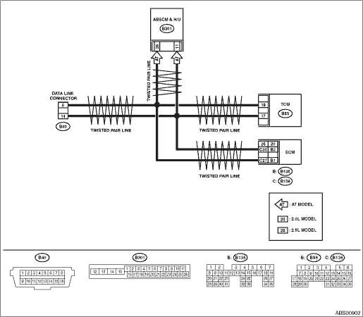
1.CHECK HARNESS CONNECTOR BETWEEN ABSCM&H/U AND TCM.
1) Turn the ignition switch to OFF.
2) Disconnect the ABSCM&H/U connectors and TCM connectors.
3) Measure the resistance of the harness connector between ABSCM&H/U and TCM.
Connector & terminal
LHD model
(B301) No. 26 — (B55) No. 18:
(B301) No. 11 — (B55) No. 17:
RHD model
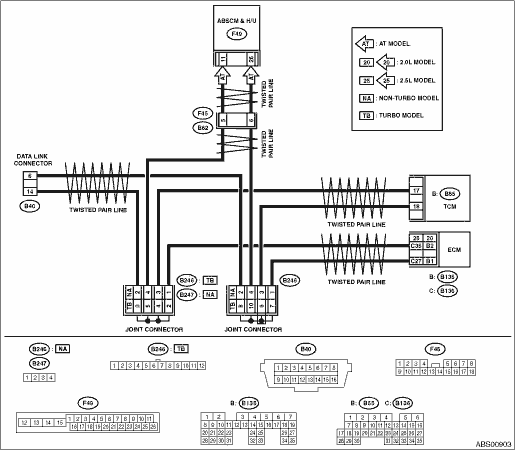
(F49) No. 26 — (B55) No. 18:
(F49) No. 11 — (B55) No. 17:
|
Is the resistance less than 0.5 Ω?
|
|
Repair or replace the harness connector between ABSCM&H/U and TCM.
|
2.CHECK HARNESS CONNECTOR BETWEEN ABSCM&H/U AND TCM FOR GROUND SHORT.
1) Measure the resistance between the ABSCM&H/U connector and chassis ground.
Connector & terminal
LHD model
(B301) No. 26 — Chassis ground:
(B301) No. 11 — Chassis ground:
RHD model
(F49) No. 26 — Chassis ground:
(F49) No. 11 — Chassis ground:
|
Is the resistance more than 1 MΩ?
|
|
Repair or replace the harness connector between ABSCM&H/U and TCM.
|
3.CHECK HARNESS CONNECTOR BETWEEN ABSCM&H/U AND TCM FOR BATTERY SHORT.
1) Turn the ignition switch to ON.
2) Measure the voltage between ABSCM&H/U connector and chassis ground.
Connector & terminal
LHD model
(B301) No. 26 (+) — Chassis ground (−):
(B301) No. 11 (+) — Chassis ground (−):
RHD model
(F49) No. 26 (+) — Chassis ground (−):
(F49) No. 11 (+) — Chassis ground (−):
|
Is the voltage less than 1.0 V?
|
|
Repair or replace the harness connector between ABSCM&H/U and TCM.
|
4.CHECK ABSCM&H/U.
1) Turn the ignition switch to OFF.
2) Connect the connector to ABSCM&H/U.
3) Measure the resistance between TCM connector terminals.
Connector & terminal
(B55) No. 17 — (B55) No. 18:
|
Is the resistance 120±6 Ω?
|
|
|
5.CHECK ABSCM&H/U CONNECTOR FOR POOR CONTACT.
|
|
Repair the poor contact of ABSCM&H/U connector.
|
Replace the ABSCM only. 
|
6.CHECK TCM.
1) Connect the connector to TCM.
2) Disconnect the ABSCM&H/U connectors.
3) Measure the resistance between the ABSCM&H/U connector terminals.
Connector & terminal
LHD model
(B301) No. 11 — No. 26:
RHD model
(F49) No. 11 — No. 26:
|
Is the resistance 120±6 Ω?
|
|
|
7.CHECK POOR CONTACT OF TCM CONNECTORS.
|
|
Repair the poor contact of TCM connector.
|
Replace the TCM.
|
9.CHECK IF TCM SYSTEM DTC P1718 IS DETECTED.
|
|
Replace the TCM.
|
Replace the ABSCM only.
|