1.CHECK OUTPUT OF ABS WHEEL SPEED SENSOR USING SUBARU SELECT MONITOR.
1) Select {Current Data Display & Save} in Subaru Select Monitor.
2) Read the ABS wheel speed sensor output corresponding to the faulty system in Subaru Select Monitor display mode.
|
Does the speed indicated on the display change in response to the speedometer reading during acceleration or deceleration when the steering wheel is in the straight-ahead position?
|
|
|
2.CHECK INSTALLATION OF ABS WHEEL SPEED SENSOR.
|
Is the ABS wheel speed sensor installation bolt tightened to 33 N·m (3.4 kgf-m, 25 ft-lb)?
|
|
Tighten the ABS wheel speed sensor installation bolts.
|
3.CHECK ABS WHEEL SPEED SENSOR GAP.
Measure the gap between the ABS wheel speed sensor protrusion and tone wheel.
|
Is the gap within the following? Front wheel: 0.3 — 0.8 mm (0.012 — 0.031 in); Rear wheel: 0.7 — 1.2 mm (0.028 — 0.047 in)
|
|
Adjust the gap.
NOTE:
Adjust the gap using spacers (Part No. 26755AA000). If spacers cannot correct the gap, replace the worn sensor or worn tone wheel.
|
4.CHECK TONE WHEEL RUNOUT.
Measure the tone wheel runout.
|
Is the runout less than 0.05 mm (0.0020 in)?
|
|
Replace the tone wheel. Front:  Rear: Rear:
|
5.CHECK POOR CONTACT IN CONNECTOR.
Turn the ignition switch to OFF.
|
Is there poor contact in connectors between ABSCM&H/U and ABS wheel speed sensor?
|
|
|
6.CHECK ABSCM&H/U.
1) Connect all connectors.
3) Perform the Inspection Mode.
|
Is the same DTC still output?
|
Replace the ABSCM only.
|
|
7.CHECK OTHER DTC DETECTION.
|
Is there any other DTC detected?
|
Perform the diagnosis according to DTC.
|
Temporary poor contact occurs.
NOTE:
Check the harness and connector between ABSCM&H/U and ABS wheel speed sensor.
|
8.CHECK ABS WHEEL SPEED SENSOR.
1) Turn the ignition switch to OFF.
2) Disconnect the connector from the ABS wheel speed sensor.
3) Measure the resistance of ABS wheel speed sensor terminals while shaking the harness lightly.
|
Is the resistance within the following? Front: 1 — 1.5 kΩ Rear: 1.025 — 1.265 kΩ
|
|
Replace the ABS wheel speed sensor. Front: Rear:
|
9.CHECK BATTERY SHORT OF ABS WHEEL SPEED SENSOR.
1) Disconnect the ABSCM&H/U connectors.
2) Measure the voltage between ABS wheel speed sensor and chassis ground.
Terminals
Front RH
No. 1 (+) — Chassis ground (−):
Front LH
No. 1 (+) — Chassis ground (−):
Rear RH
No. 1 (+) — Chassis ground (−):
Rear LH
No. 1 (+) — Chassis ground (−):
|
Is the voltage less than 1 V?
|
|
Replace the ABS wheel speed sensor. Front: Rear:
|
10.CHECK BATTERY SHORT OF ABS WHEEL SPEED SENSOR.
1) Turn the ignition switch to ON.
2) Measure the voltage between ABS wheel speed sensor and chassis ground.
Terminals
Front RH
No. 1 (+) — Chassis ground (−):
Front LH
No. 1 (+) — Chassis ground (−):
Rear RH
No. 1 (+) — Chassis ground (−):
Rear LH
No. 1 (+) — Chassis ground (−):
|
Is the voltage less than 1 V?
|
|
Replace the ABS wheel speed sensor. Front: Rear:
|
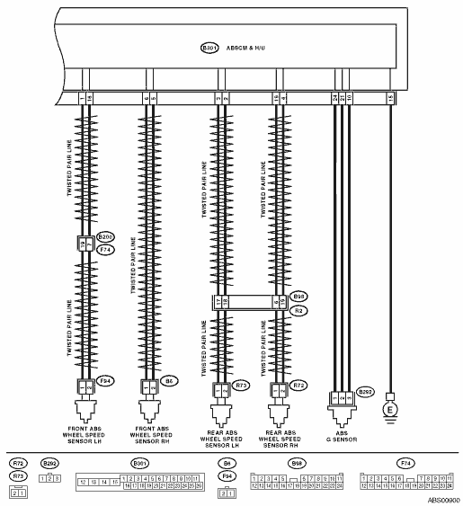
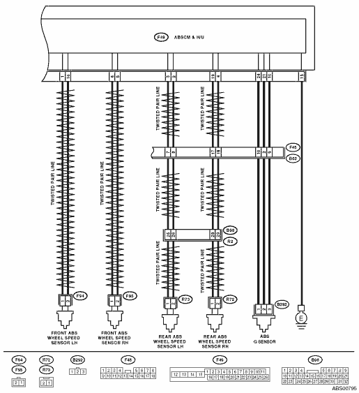
11.CHECK HARNESS CONNECTOR BETWEEN ABSCM&H/U AND ABS WHEEL SPEED SENSOR.
1) Turn the ignition switch to OFF.
2) Connect the connector to the ABS wheel speed sensor.
3) Measure the resistance between ABSCM&H/U connector terminals.
Connector & terminal
DTC 21
LHD model
(B301) No. 6 — No. 5:
RHD model
(F49) No. 6 — No. 5:
DTC 23
LHD model
(B301) No. 1 — No. 16:
RHD model
(F49) No. 1 — No. 16:
DTC 25
LHD model
(B301) No. 19 — No. 4:
RHD model
(F49) No. 19 — No. 4:
DTC 27
LHD model
(B301) No. 3 — No. 2:
RHD model
(F49) No. 3 — No. 2:
|
Is the resistance within the following? Front: 1 — 1.5 kΩ Rear: 1.025 — 1.265 kΩ
|
|
Repair the harness connector between ABSCM&H/U and ABS wheel speed sensor.
|
12.CHECK BATTERY SHORT OF HARNESS.
Measure the voltage between ABSCM&H/U connector and chassis ground.
Connector & terminal
DTC 21
LHD model
(B301) No. 6 (+) — Chassis ground (−):
RHD model
(F49) No. 6 (+) — Chassis ground (−):
DTC 23
LHD model
(B301) No. 1 (+) — Chassis ground (−):
RHD model
(F49) No. 1 (+) — Chassis ground (−):
DTC 25
LHD model
(B301) No. 19 (+) — Chassis ground (−):
RHD model
(F49) No. 19 (+) — Chassis ground (−):
DTC 27
LHD model
(B301) No. 3 (+) — Chassis ground (−):
RHD model
(F49) No. 3 (+) — Chassis ground (−):
|
Is the voltage less than 1 V?
|
|
Repair the harness between ABSCM&H/U and ABS wheel speed sensor.
|
13.CHECK BATTERY SHORT OF HARNESS.
1) Turn the ignition switch to ON.
2) Measure the voltage between ABSCM&H/U connector and chassis ground.
Connector & terminal
DTC 21
LHD model
(B301) No. 6 (+) — Chassis ground (−):
RHD model
(F49) No. 6 (+) — Chassis ground (−):
DTC 23
LHD model
(B301) No. 1 (+) — Chassis ground (−):
RHD model
(F49) No. 1 (+) — Chassis ground (−):
DTC 25
LHD model
(B301) No. 19 (+) — Chassis ground (−):
RHD model
(F49) No. 19 (+) — Chassis ground (−):
DTC 27
LHD model
(B301) No. 3 (+) — Chassis ground (−):
RHD model
(F49) No. 3 (+) — Chassis ground (−):
|
Is the voltage less than 1 V?
|
|
Repair the harness between ABSCM&H/U and ABS wheel speed sensor.
|
14.CHECK INSTALLATION OF ABS WHEEL SPEED SENSOR.
|
Is the ABS wheel speed sensor installation bolt tightened to 33 N·m (3.4 kgf-m, 25 ft-lb)?
|
|
Tighten the ABS wheel speed sensor installation bolts.
|
15.CHECK ABS WHEEL SPEED SENSOR GAP.
Measure the gap between the ABS wheel speed sensor protrusion and tone wheel.
|
Is the gap within the following? Front wheel: 0.3 — 0.8 mm (0.012 — 0.031 in); Rear wheel: 0.7 — 1.2 mm (0.028 — 0.047 in)
|
|
Adjust the gap.
NOTE:
Adjust the gap using spacers (Part No. 26755AA000). If spacers cannot correct the gap, replace the worn sensor or worn tone wheel.
|
16.CHECK TONE WHEEL RUNOUT.
Measure the tone wheel runout.
|
Is the runout less than 0.05 mm (0.0020 in)?
|
|
Replace the tone wheel. Front: Rear:
|
17.CHECK GROUND SHORT OF ABS WHEEL SPEED SENSOR.
1) Turn the ignition switch to ON.
2) Measure the resistance between ABS wheel speed sensor and chassis ground.
Terminals
Front RH
No. 1 — Chassis ground:
Front LH
No. 1 — Chassis ground:
Rear RH
No. 1 — Chassis ground:
Rear LH
No. 1 — Chassis ground:
|
Is the resistance more than 1 MΩ?
|
|
|
18.CHECK GROUND SHORT OF HARNESS.
1) Turn the ignition switch to OFF.
2) Connect the connector to the ABS wheel speed sensor.
3) Measure the resistance between ABSCM&H/U connectors and chassis ground.
Connector & terminal
DTC 21
LHD model
(B301) No. 6 — Chassis ground:
RHD model
(F49) No. 6 — Chassis ground:
DTC 23
LHD model
(B301) No. 1 — Chassis ground:
RHD model
(F49) No. 1 — Chassis ground:
DTC 25
LHD model
(B301) No. 19 — Chassis ground:
RHD model
(F49) No. 19 — Chassis ground:
DTC 27
LHD model
(B301) No. 3 — Chassis ground:
RHD model
(F49) No. 3 — Chassis ground:
|
Is the resistance more than 1 MΩ?
|
|
Repair the harness between ABSCM&H/U and ABS wheel speed sensor. Replace the ABSCM&H/U.
|
19.CHECK POOR CONTACT IN CONNECTOR.
|
Is there poor contact in connectors between ABSCM&H/U and ABS wheel speed sensor?
|
|
|
20.CHECK ABSCM&H/U.
1) Connect all connectors.
3) Perform the Inspection Mode.
|
Is the same DTC still output?
|
|
|
21.CHECK OTHER DTC DETECTION.
|
Is there any other DTC detected?
|
Perform the diagnosis according to DTC.
|
Temporary poor contact occurs.
NOTE:
Check the harness and connector between ABSCM&H/U and ABS wheel speed sensor.
|