|
|
Is the ignition switch ON?
|
|
Turn the ignition switch to ON, and select ABS mode using Subaru Select Monitor.
|
2.CHECK BATTERY.
1) Turn the ignition switch to OFF.
2) Measure the battery voltage.
|
Is the voltage more than 11 V?
|
|
Charge or replace the battery.
|
3.CHECK BATTERY TERMINAL.
|
Is there poor contact at the battery terminal?
|
Repair or tighten the battery terminal.
|
|
4.CHECK SUBARU SELECT MONITOR COMMUNICATION.
1) Turn the ignition switch to ON.
2) Using the Subaru Select Monitor, check whether communication to other systems can be executed normally.
|
Are the system name and model year displayed on Subaru Select Monitor?
|
|
|
5.CHECK SUBARU SELECT MONITOR COMMUNICATION.
1) Turn the ignition switch to OFF.
2) Disconnect the ABSCM&H/U connectors.
3) Turn the ignition switch to ON.
4) Check whether communication to other systems can be executed normally.
|
Are the system name and model year displayed on Subaru Select Monitor?
|
Replace the ABSCM&H/U. 
|
|
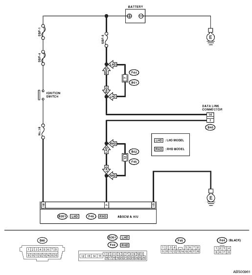
6.CHECK HARNESS CONNECTOR BETWEEN EACH CONTROL MODULE AND DATA LINK CONNECTOR.
1) Turn the ignition switch to OFF.
2) Disconnect the ABSCM&H/U, ECM and TCM.
3) Measure the resistance between data link connector and chassis ground.
Connector & terminal
(B40) No. 7— Chassis ground:
|
Is the resistance more than 1 MΩ?
|
|
Repair the harness and connector between each control module and data link connector.
|
7.CHECK OUTPUT SIGNAL FOR ABSCM&H/U.
1) Turn the ignition switch to ON.
2) Measure the voltage between ABSCM&H/U connector and chassis ground.
Connector & terminal
(B40) No. 7(+) — Chassis ground (−):
|
Is the voltage less than 1 V?
|
|
Repair the harness and connector between each control module and data link connector.
|
8.CHECK HARNESS CONNECTOR BETWEEN ABSCM&H/U AND DATA LINK CONNECTOR.
Measure the resistance between ABSCM&H/U connector and data link connector.
Connector & terminal
LHD model
(B301) No. 7 — (B40) No. 7:
RHD model
(F49) No. 7 — (B40) No. 7:
|
Is the resistance less than 0.5 Ω?
|
|
Repair harness and connector between ABSCM&H/U and data link connector.
|
9.CHECK INSTALLATION OF ABSCM&H/U CONNECTOR.
Turn the ignition switch to OFF.
|
Is the ABSCM&H/U connector inserted into ABSCM&H/U until the clamp locks onto it?
|
|
Insert ABSCM&H/U connector into ABSCM&H/U.
|
10.CHECK POWER SUPPLY CIRCUIT.
1) Turn the ignition switch to ON. (engine OFF)
2) Measure the ignition power supply voltage between ABSCM&H/U connector and chassis ground.
Connector & terminal
LHD model
(B301) No. 18 (+) — Chassis ground (−):
RHD model
(F49) No. 18 (+) — Chassis ground (−):
|
Is the voltage 10 — 15 V?
|
|
Repair open circuit of harness between ABSCM&H/U and battery.
|
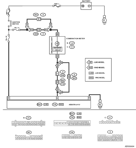
11.CHECK HARNESS CONNECTOR BETWEEN ABSCM&H/U AND CHASSIS GROUND.
1) Turn the ignition switch to OFF.
2) Disconnect the ABSCM&H/U connectors.
3) Measure the resistance of the harness between ABSCM&H/U and chassis ground.
Connector & terminal
LHD model
(B301) No. 15 — Chassis ground:
RHD model
(F49) No. 15 — Chassis ground:
|
Is the resistance less than 0.5 Ω?
|
|
Repair the open circuit of the harness between ABSCM&H/U and inhibitor side connector, and poor contact of coupling connector.
|
12.CHECK POOR CONTACT IN CONNECTOR.
|
Is there poor contact in control module power supply, ground circuit and data link connector?
|
|
Replace the ABSCM only.
|