1.CHECK OUTPUT OF YAW RATE & LATERAL G SENSOR USING SUBARU SELECT MONITOR.
1) Stop the vehicle on a flat road.
2) Select {Current Data Display & Save} in Subaru Select Monitor.
3) Read the yaw rate & lateral G sensor output on the Subaru Select Monitor display.
|
Is the resistance 2.5±0.2 V?
|
|
|
2.CHECK POOR CONTACT OF CONNECTOR.
Turn the ignition switch to OFF.
|
Is there poor contact in connector between VDCCM and yaw rate & lateral G sensor?
|
|
|
3.CHECK VDCCM.
1) Connect all connectors.
3) Perform the Inspection Mode.
|
In the current diagnosis, is the same DTC displayed again?
|
Replace the VDCCM. 
|
|
4.CHECK ANY OTHER DTC ON DISPLAY.
|
Are other DTCs displayed?
|
Go to the diagnosis corresponding to the DTC.
|
Temporary poor contact occurs.
|
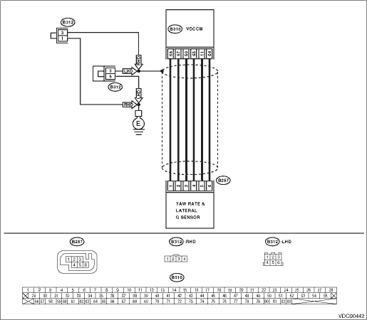
5.CHECK YAW RATE & LATERAL G SENSOR INPUT VOLTAGE.
1) Turn the ignition switch to OFF.
2) Remove the console box.
3) Disconnect the connector from yaw rate & lateral G sensor.
4) Turn the ignition switch to ON.
5) Measure the voltage between yaw rate & lateral G sensor connector terminals.
Connector & terminal
(B257) No. 3 (+) — No. 6 (−):
|
Is the voltage 10 — 15 V?
|
|
Repair the harness or connector between yaw rate & lateral G sensor and VDCCM.
|
6.CHECK YAW RATE & LATERAL G SENSOR.
1) Turn the ignition switch to OFF.
2) Measure the resistance between yaw rate & lateral G sensor connector terminals.
|
Is the resistance between 4.3 — 4.9 kΩ?
|
|
Replace the yaw rate & lateral G sensor.
|
7.CHECK OPEN CIRCUIT FOR OUTPUT HARNESS AND GROUND HARNESS OF YAW RATE & LATERAL G SENSOR.
1) Connect the connector to the yaw rate & lateral G sensor.
2) Disconnect the connectors from VDCCM.
3) Measure the resistance between the VDCCM connector terminals.
|
Is the resistance between 4.3 — 4.9 kΩ?
|
|
Repair the harness between yaw rate & lateral G sensor and VDCCM.
|
8.CHECK GROUND SHORT IN YAW RATE & LATERAL G SENSOR HARNESS.
1) Disconnect the connector from yaw rate & lateral G sensor.
2) Measure the resistance between VDCCM connector and chassis ground.
Connector & terminal
(B310) No. 11 — Chassis ground:
|
Is the resistance 1 MΩ or more?
|
|
Repair the harness between yaw rate & lateral G sensor and VDCCM.
|
9.CHECK YAW RATE & LATERAL G SENSOR.
1) Turn the ignition switch to OFF.
2) Remove the yaw rate & lateral G sensors from vehicle.
3) Connect the connector to the yaw rate & lateral G sensor.
4) Connect the connector to the VDCCM.
5) Turn the ignition switch to ON.
6) Measure the voltage between yaw rate & lateral G sensor connector terminals.
Connector & terminal
(B257) No. 5 (+) — No. 6 (−):
|
Is the voltage 2.3 — 2.7 V when yaw rate & lateral G sensor is on a level?
|
|
Replace the yaw rate & lateral G sensor.
|
10.CHECK YAW RATE & LATERAL G SENSOR.
Measure the voltage between yaw rate & lateral G sensor connector terminals.
Connector & terminal
(B257) No. 5 (+) — No. 6 (−):
|
Is the voltage 3.3 — 3.7 V when yaw rate & lateral G sensor is inclined 90° to the left?
|
|
Replace the yaw rate & lateral G sensor.
|
11.CHECK YAW RATE & LATERAL G SENSOR.
Measure the voltage between yaw rate & lateral G sensor connector terminals.
Connector & terminal
(B257) No. 5 (+) — No. 6 (−):
|
Is the voltage 1.3 — 1.7 V when yaw rate & lateral G sensor is inclined 90° to the right?
|
|
Replace the yaw rate & lateral G sensor.
|
12.CHECK POOR CONTACT OF CONNECTOR.
|
Is there poor contact in connector between VDCCM and yaw rate & lateral G sensor?
|
|
|
13.CHECK VDCCM.
1) Connect all connectors.
3) Perform the Inspection Mode.
|
In the current diagnosis, is the same DTC displayed again?
|
Replace the VDCCM.
|
|
14.CHECK ANY OTHER DTC ON DISPLAY.
|
Are other DTCs displayed?
|
Go to the diagnosis corresponding to the DTC.
|
Temporary poor contact occurs.
|