1.CHECK GROUND SHORT CIRCUIT OF HARNESS.
1) Turn the ignition switch to OFF.
2) Disconnect the connectors from VDCCM.
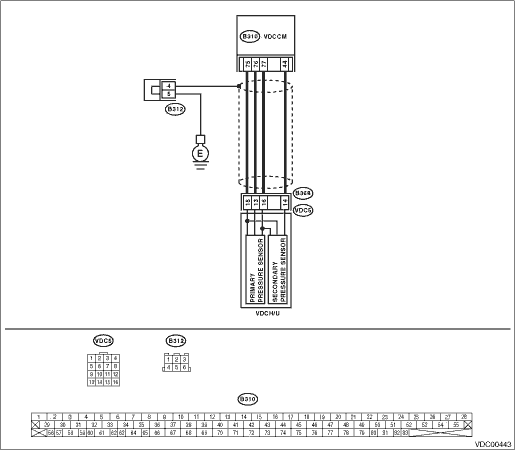
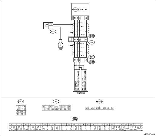
3) Disconnect the connectors (B368) (LHD model) and (F91) (RHD model) from VDCH/U.
4) Measure the resistance between VDCH/U connector and chassis ground.
Connector & terminal
LHD
(B368) No. 13 — Chassis ground:
(B368) No. 14 — Chassis ground:
RHD
(F91) No. 13 — Chassis ground:
(F91) No. 14 — Chassis ground:
|
Is the resistance 1 MΩ or more?
|
|
Repair the harness between VDCH/U and VDCCM.
|
2.CHECK BATTERY SHORT OF HARNESS.
Measure the voltage between VDCH/U connector and chassis ground.
Connector & terminal
LHD
(B368) No. 13 (+) — Chassis ground (−):
(B368) No. 14 (+) — Chassis ground (−):
RHD
(F91) No. 13 (+) — Chassis ground (−):
(F91) No. 14 (+) — Chassis ground (−):
|
Is the voltage less than 0.5 V?
|
|
Repair the harness between VDCH/U and VDCCM.
|
3.CHECK BATTERY SHORT OF HARNESS.
1) Turn the ignition switch to ON.
2) Measure the voltage between VDCH/U connector and chassis ground.
Connector & terminal
LHD
(B368) No. 13 (+) — Chassis ground (−):
(B368) No. 14 (+) — Chassis ground (−):
RHD
(F91) No. 13 (+) — Chassis ground (−):
(F91) No. 14 (+) — Chassis ground (−):
|
Is the voltage less than 0.5 V?
|
|
Repair the harness between VDCH/U and VDCCM.
|
4.CHECK INPUT VOLTAGE OF PRESSURE SENSOR.
1) Turn the ignition switch to OFF.
2) Disconnect the connectors from VDCCM.
3) Remove the cover from VDCCM. 
4) Connect the connector to the VDCCM.
5) Connect all connectors.
6) Turn the ignition switch to ON.
7) Do not depress the brake pedal.
8) Measure the voltage between VDCCM connector terminals.
Connector & terminal
(B310) No. 76 (+) — No. 75 (−):
(B310) No. 44 (+) — No. 75 (−):
|
Is the voltage 0.48 — 0.72 V?
|
|
Replace the VDCH/U.
|
5.CHECK FOR BRAKE FLUID LEAKS.
Check for fluid leaks between brake master cylinder and VDCH/U.
|
|
|
|
6.CHECK BRAKE MASTER CYLINDER.
Check the brake master cylinder oil pressure.
|
|
|
Replace the master cylinder.
|
7.CHECK BRAKE PEDAL STROKE.
Measure the stroke of the brake pedal at 50 kg (110 lb).
|
Is the stroke less than 105 mm (4.13 in)?
|
|
Bleed the air of brake system.
|
8.CHECK INPUT VOLTAGE OF PRESSURE SENSOR.
1) Depress the brake pedal with the force of 50 kg (110 lb).
2) Measure the voltage between VDCCM connector terminals.
Connector & terminal
(B310) No. 76 (+) — No. 75 (−):
(B310) No. 44 (+) — No. 75 (−):
|
Is the voltage less than 0.2 V?
|
|
Replace the VDCH/U.
|
9.CHECK POOR CONTACT OF CONNECTOR.
|
Is there poor contact in connectors between VDCCM and pressure sensor?
|
|
|
10.CHECK VDCCM.
1) Connect all connectors.
3) Perform the Inspection Mode.
|
In the current diagnosis, is the same DTC displayed again?
|
Replace the VDCCM.
|
|
11.CHECK ANY OTHER DTC ON DISPLAY.
|
Are other DTCs displayed?
|
Go to the diagnosis corresponding to the DTC.
|
Temporary poor contact occurs.
|