DTC DETECTING CONDITION:
• Defective motor relay
• Defective harness connector
TROUBLE SYMPTOM:
• ABS does not operate.
• VDC does not operate.
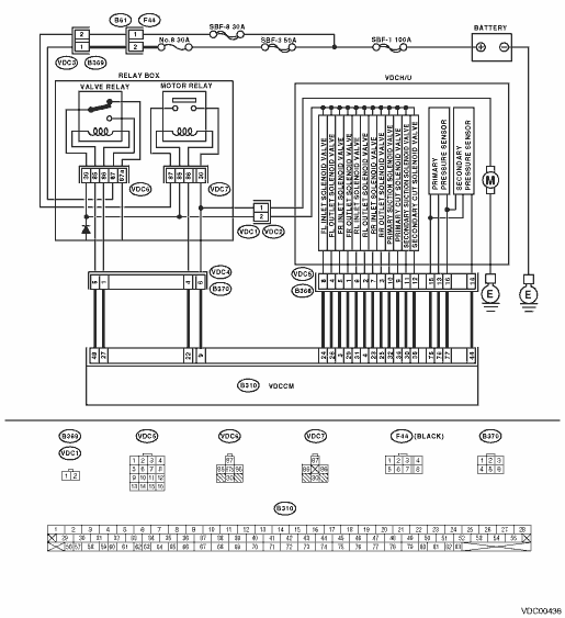
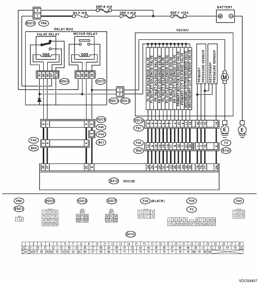
WIRING DIAGRAM:
• LHD model

• RHD model
| STEP | CHECK | YES | NO |
|
Is the motor ground terminal tightened to 33±10 N·m (3.3±1.0 kgf-m, 24±7 ft-lb)? |
|
Tighten the motor ground terminal clamp. |
|
|
Is the resistance 1 MΩ or more? |
|
Replace the motor relay. |
|
|
Is the resistance 1 MΩ or more? |
|
Replace the motor relay. |
|
|
Is the resistance 1 MΩ or more? |
|
Replace the relay box. |
|
|
Is the voltage less than 1 V? |
|
Replace the relay box. |
|
|
Is the voltage less than 1 V? |
|
Replace the relay box. |
|
|
Is the resistance 1 MΩ or more? |
|
Repair the harness between VDCCM and relay box. Check the fuse SBF holder. |
|
|
Is the voltage less than 1 V? |
|
Repair the harness between VDCCM and relay box. |
|
|
Is the voltage less than 1 V? |
|
Repair the harness between VDCCM and relay box. |
|
|
Is there poor contact in connectors between the VDCH/U, relay box and VDCCM? |
Repair the connector. |
|
|
|
In the current diagnosis, is the same DTC displayed again? |
Replace the VDCCM. |
|
|
|
Are other DTCs displayed? |
Go to the diagnosis corresponding to the DTC. |
Temporary poor contact occurs. NOTE: The ABS warning light will remain lit until the vehicle reaches approximately 12 km/h (7.46 MPH) even when the memory is cleared. This is normal. |
