1.CHECK RESISTANCE OF VALVE RELAY.
1) Turn the ignition switch to OFF.
2) Remove the valve relay from the relay box.
3) Measure the resistance between valve relay terminals.
|
Is the resistance between 93 — 113 Ω?
|
|
|
2.CHECK CONTACT POINT OF VALVE RELAY.
1) Connect the battery to the valve relay terminals No. 85 and No. 86.
2) Measure the resistance between valve relay terminals.
|
Is the resistance less than 0.5 Ω?
|
|
|
3.CHECK CONTACT POINT OF VALVE RELAY.
Measure the resistance between valve relay terminals.
|
Is the resistance 1 MΩ or more?
|
|
|
4.CHECK CONTACT POINT OF VALVE RELAY.
1) Disconnect the battery from the valve relay terminals.
2) Measure the resistance between valve relay terminals.
|
Is the resistance 1 MΩ or more?
|
|
|
5.CHECK CONTACT POINT OF VALVE RELAY.
Measure the resistance between valve relay terminals.
|
Is the resistance less than 0.5 Ω?
|
|
|
6.CHECK VALVE RELAY SHORT.
Measure the resistance between valve relay terminals.
|
Is the resistance 1 MΩ or more?
|
|
|
7.CHECK POWER SUPPLY FOR VALVE RELAY.
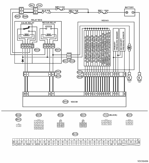
1) Disconnect the connectors (B369) (LHD model) and (F89) (RHD model) from relay box.
2) Turn the ignition switch to ON.
3) Measure the voltage between the relay box connector and chassis ground.
Connector & terminal
LHD
(B369) No. 1 (+) — Chassis ground (−):
RHD
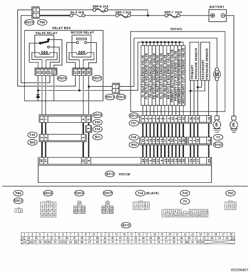
(F89) No. 1 (+) — Chassis ground (−):
|
Is the voltage 10 — 15 V?
|
|
Repair the harness between battery and relay box connector. Check fuse No. 8.
|
8.CHECK GROUND SHORT AND OPEN CIRCUIT ON POWER SUPPLY CIRCUIT OF RELAY BOX.
1) Disconnect the connector (VDC1) from VDCH/U.
2) Connect the connectors (B369) (LHD model) and (F89) (RHD model) to relay box.
3) Turn the ignition switch to ON.
4) Measure the relay box voltage.
Connector & terminal
Valve relay installation point No. 87 (+) — Chassis ground (−):
|
Is the voltage 10 — 15 V?
|
|
Replace the relay box and check fuse No. 8.
|
9.CHECK OPEN CIRCUIT OF RELAY BOX CONTROL CIRCUIT.
1) Turn the ignition switch to OFF.
2) Disconnect the connectors (B370) (LHD model) and (F90) (RHD model) from relay box.
3) Measure the resistance between the relay box connector and valve relay installation point.
Connector & terminal
(VDC4) No. 5 — Valve relay installation point No. 85:
(VDC4) No. 1 — Valve relay installation point No. 86:
|
Is the resistance less than 0.5 Ω?
|
|
|
10.CHECK GROUND SHORT CIRCUIT OF THE RELAY BOX CONTACT POINT CIRCUIT.
Measure the resistance between the relay box connector and chassis ground.
Connector & terminal
(VDC4) No. 5 — Chassis ground:
(VDC4) No. 1 — Chassis ground:
|
Is the resistance 1 MΩ or more?
|
|
Replace the relay box and check fuse SBF6.
|
11.CHECK OPEN CIRCUIT OF VALVE RELAY CONTROL SYSTEM HARNESS CIRCUIT.
1) Turn the ignition switch to OFF.
2) Disconnect the connectors from VDCCM.
3) Measure the resistance between VDCCM connector and relay box connector.
Connector & terminal
LHD
(B310) No. 48 — (B370) No. 5:
(B310) No. 27 — (B370) No. 1:
RHD
(B310) No. 48 — (F90) No. 5:
(B310) No. 27 — (F90) No. 1:
|
Is the resistance less than 0.5 Ω?
|
|
Repair the harness between VDCCM and relay box.
|
12.CHECK GROUND SHORT OF THE VALVE RELAY CONTROL SYSTEM HARNESS.
Measure the resistance between VDCCM connector and chassis ground.
Connector & terminal
(B310) No. 48 — Chassis ground:
(B310) No. 27 — Chassis ground:
|
Is the resistance 1 MΩ or more?
|
|
Repair the harness between VDCCM and relay box.
|
13.CHECK OPEN CIRCUIT OF THE RELAY BOX CONTACT POINT CIRCUIT.
Measure the resistance between the VDCH/U connector and valve relay installation point.
Connector & terminal
(VDC1) No. 2 — Valve relay installation point No. 30:
|
Is the resistance less than 0.5 Ω?
|
|
|
14.CHECK GROUND SHORT CIRCUIT IN THE RELAY BOX CONTACT POINT CIRCUIT.
Measure the resistance between VDCH/U connector and chassis ground.
Connector & terminal
(VDC1) No. 2 — Chassis ground:
|
Is the resistance 1 MΩ or more?
|
|
Replace the relay box and check fuse No. 8.
|
15.CHECK RESISTANCE OF HOLD VALVE AND CUT SOLENOID VALVE.
1) Disconnect the connector from VDCH/U.
2) Measure the resistance between VDCH/U connector terminals.
Connector & terminal
(VDC5) No. 8 — (VDC2) No. 2:
(VDC5) No. 5 — (VDC2) No. 2:
(VDC5) No. 6 — (VDC2) No. 2:
(VDC5) No. 7 — (VDC2) No. 2:
(VDC5) No. 9 — (VDC2) No. 2:
(VDC5) No. 12 — (VDC2) No. 2:
|
Is the resistance between 8.04 — 9.04 Ω?
|
|
Replace the VDCH/U. 
|
16.CHECK RESISTANCE OF DECOMPRESSION VALVE.
Measure the resistance between VDCH/U connector terminals.
Connector & terminal
(VDC5) No. 4 — (VDC2) No. 2:
(VDC5) No. 1 — (VDC2) No. 2:
(VDC5) No. 2 — (VDC2) No. 2:
(VDC5) No. 3 — (VDC2) No. 2:
(VDC5) No. 10 — (VDC2) No. 2:
(VDC5) No. 11 — (VDC2) No. 2:
|
Is the resistance between 4.04 — 4.54 Ω?
|
|
Replace the VDCH/U.
|
17.CHECK SOLENOID VALVE GROUND SHORT.
Measure the resistance between VDCH/U connector and chassis ground.
Connector & terminal
(VDC2) No. 2 — Chassis ground:
|
Is the resistance 1 MΩ or more?
|
|
Replace the VDCH/U and check all of the fuses.
|
18.CHECK GROUND SHORT CIRCUIT OF HARNESS.
1) Turn the ignition switch to OFF.
2) Measure the resistance between VDCCM connector and chassis ground.
Connector & terminal
(B310) No. 3 — Chassis ground:
(B310) No. 24 — Chassis ground:
(B310) No. 23 — Chassis ground:
(B310) No. 31 — Chassis ground:
(B310) No. 35 — Chassis ground:
(B310) No. 34 — Chassis ground:
(B310) No. 29 — Chassis ground:
(B310) No. 26 — Chassis ground:
(B310) No. 25 — Chassis ground:
(B310) No. 4 — Chassis ground:
(B310) No. 30 — Chassis ground:
(B310) No. 32 — Chassis ground:
|
Is the resistance 1 MΩ or more?
|
|
Repair the harness between VDCH/U and VDCCM.
|
19.CHECK HARNESS CONNECTOR BETWEEN VDCCM AND VDCH/U.
1) Connect the connectors (B368) (LHD model) and (F91) (RHD model) to VDCH/U.
2) Measure the resistance between the VDCCM connector and VDCH/U.
Connector & terminal
(B310) No. 3 — (VDC2) No. 2:
(B310) No. 24 — (VDC2) No. 2:
(B310) No. 23 — (VDC2) No. 2:
(B310) No. 31 — (VDC2) No. 2:
(B310) No. 35 — (VDC2) No. 2:
(B310) No. 34 — (VDC2) No. 2:
|
Is the resistance between 8.0 — 10.0 Ω?
|
|
Repair the harness and connector between the VDCH/U and the VDCCM.
|
20.CHECK HARNESS CONNECTOR BETWEEN VDCCM AND VDCH/U.
Measure the resistance between the VDCCM connector terminals.
Connector & terminal
(B310) No. 29 — (VDC2) No. 2:
(B310) No. 26 — (VDC2) No. 2:
(B310) No. 25 — (VDC2) No. 2:
(B310) No. 4 — (VDC2) No. 2:
(B310) No. 30 — (VDC2) No. 2:
(B310) No. 32 — (VDC2) No. 2:
|
Is the resistance between 4.0 — 6.0 Ω?
|
|
Repair the harness connector between the VDCH/U and the VDCCM.
|
21.CHECK POOR CONTACT OF CONNECTOR.
|
Is there poor contact in connector between the VDCCM and VDCH/U?
|
|
|
22.CHECK VDCCM.
1) Connect all connectors.
3) Perform the Inspection Mode.
|
In the current diagnosis, is the same DTC displayed again?
|
Replace the VDCCM.
|
|
23.CHECK ANY OTHER DTC ON DISPLAY.
|
Are other DTCs displayed?
|
Go to the diagnosis corresponding to the DTC.
|
Temporary poor contact occurs.
|