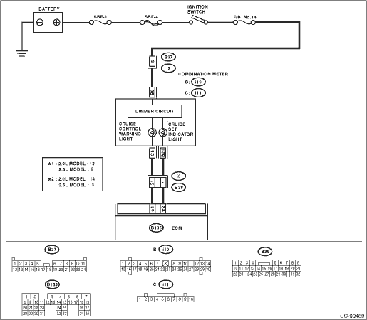
1.CHECK CRUISE INDICATOR LIGHT CIRCUIT.
1) Turn the ignition switch to OFF.
2) Disconnect the harness connector of the combination meter.
3) Turn the ignition switch to ON.
4) Measure the voltage between harness connector terminal and chassis ground.
Connector & terminal
(i10) No. 9 (+) — Chassis ground (−):
|
Is the voltage 10 V or more?
|
|
• Check fuse No. 13 (in fuse & relay box).
• Check for open or shorted circuits between the combination meter and fuse & relay box.
|
2.CHECK CRUISE INDICATOR LIGHT CIRCUIT.
1) Turn the ignition switch to OFF.
2) Disconnect the harness connector of ECM.
3) Measure the resistance between the ECM harness connector and the combination meter harness connector.
Connector & terminal
2.0 L model
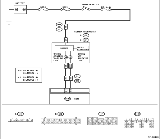
(B135) No. 13 — (i11) No. 5:
(B135) No. 14 — (i10) No. 21:
2.5 L model
(B135) No. 6 — (i11) No. 5:
(B135) No. 3 — (i10) No. 21:
|
Is the resistance less than 10 Ω?
|
|
|
3.CHECK CRUISE INDICATOR LIGHT CIRCUIT.
Connect the ECM harness connector terminal to ground using a suitable lead wire.
Connector & terminal
2.0 L model
(B135) No. 13 — Chassis ground:
(B135) No. 14 — Chassis ground:
2.5 L model
(B135) No. 6 — Chassis ground:
(B135) No. 3 — Chassis ground:
|
Does the cruise indicator light illuminate?
|
Check poor contact of ECM connector.
|
Replace the meter main assembly.
|