|
|
Is the ignition switch ON?
|
|
Turn the ignition switch to ON, and select the airbag mode using the Subaru Select Monitor.
|
2.CHECK BATTERY.
1) Turn the ignition switch to OFF.
2) Measure the battery voltage.
|
Is the voltage 11 V or more?
|
|
Charge or replace the battery.
|
3.CHECK BATTERY TERMINAL.
|
Is there poor contact at the battery terminal?
|
Repair or tighten the battery terminal.
|
|
4.CHECK SUBARU SELECT MONITOR COMMUNICATION.
1) Turn the ignition switch to ON.
2) Using the Subaru Select Monitor, check whether communication to other systems can be executed normally.
|
Are the system name and model year displayed on Subaru Select Monitor?
|
|
|
5.CHECK SUBARU SELECT MONITOR COMMUNICATION.
1) Turn the ignition switch to OFF.
2) Disconnect the airbag control module connector.
3) Turn the ignition switch to ON.
4) Check whether communication to other systems can be executed normally.
|
Are the system name and model year displayed on Subaru Select Monitor?
|
Replace the airbag control module. 
|
|
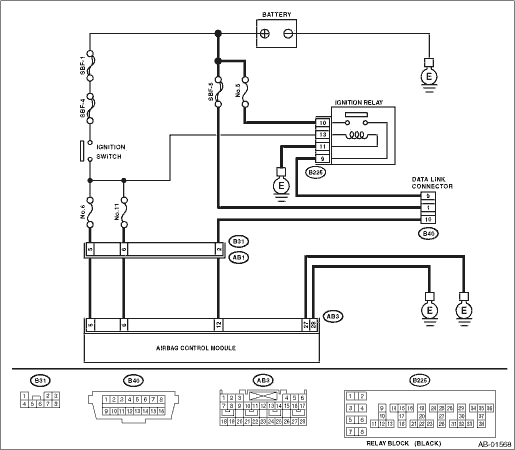
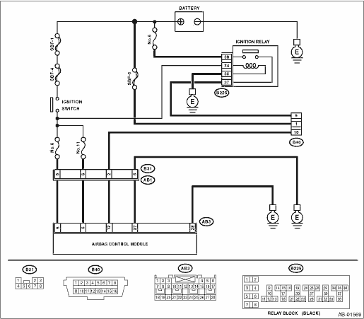
6.CHECK HARNESS CONNECTOR BETWEEN EACH CONTROL MODULE AND DATA LINK CONNECTOR.
1) Turn the ignition switch to OFF.
2) Disconnect the airbag control module, ABSCM&H/U, ECM and TCM.
3) Measure the resistance between data link connector and chassis ground.
Connector & terminal
(B40) No. 10 — Chassis ground:
|
Is the resistance 1 MΩ or more?
|
|
Repair the harness and connector between each control module and data link connector. (Replace the harness without repairing the airbag harness.)
|
7.CHECK OUTPUT SIGNAL TO THE AIRBAG CONTROL MODULE.
1) Turn the ignition switch to ON in the condition of step 6.
2) Measure the voltage between data link connector and chassis ground.
Connector & terminal
(B40) No. 10 (+) — Chassis ground (−):
|
Is the voltage less than 1 V?
|
|
Repair the harness and connector between each control module and data link connector. (Replace the harness without repairing the airbag harness.)
|
8.CHECK THE HARNESS BETWEEN THE AIRBAG CONTROL MODULE AND DATA LINK CONNECTOR.
1) Turn the ignition switch to OFF, disconnect the battery ground cable, and wait for 20 seconds or more.
2) Disconnect the connector (AB3) from airbag control module.
3) Connect connector (1R) in the test harness R to the connector (AB3).
4) Measure resistance between connector (4R) in the test harness R and data link connector.
Connector & terminal
(4R) No. 18 — (B40) No. 10:
|
Is the resistance less than 10 Ω?
|
|
Repair the harness between the airbag control module and the data link connector. Or replace the airbag main harness along with the bulkhead harness.
|
9.CHECK POWER SUPPLY CIRCUIT.
1) Turn the ignition switch to ON.
2) Measure the voltage between connector (2R) in the test harness R and chassis ground.
Connector & terminal
(2R) No. 1 (+) — Chassis ground (−):
(2R) No. 6 (+) — Chassis ground (−):
|
Is the voltage 10 V or more?
|
|
Repair the harness between the airbag control module and the battery. Or replace the airbag main harness along with the bulkhead harness.
|
10.CHECK BETWEEN THE AIRBAG CONTROL MODULE AND CHASSIS GROUND.
1) Turn the ignition switch to OFF.
2) Measure resistance between the connector (2R) in the test harness R and chassis ground.
Connector & terminal
(2R) No. 10 — Chassis ground:
(2R) No. 11 — Chassis ground:
|
Is the resistance less than 10 Ω?
|
|
Repair the harness between the airbag control module and the chassis ground. Or replace the airbag main harness along with the bulkhead harness.
|
11.CHECK POOR CONTACT OF CONNECTOR.
|
Is there poor contact in control module power supply, ground circuit and data link connector?
|
Repair the connector. (For airbag system connectors, do not repair but replace the entire harness.)
|
Replace the only airbag control module.
|