1.CHECK THE POWER SUPPLY OF THE AUTO A/C CONTROL MODULE.
1) Turn the ignition switch to ON.
2) Set the air flow control dial to the VENT position.
3) Press the defroster switch and measure the voltage between the auto A/C control module and the chassis ground when switching from VENT to DEF.
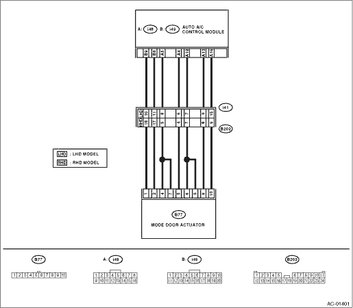
Connector & terminal
(i49) No. 9 (+) — Chassis ground (−):
|
Is the voltage 12 V or more?
|
|
Replace the auto A/C control module.
|
2.CHECK THE POWER SUPPLY OF THE ACTUATOR.
1) Set the air flow control dial to the VENT position.
2) Press the defroster switch and measure the voltage between the mode door actuator harness connector and the chassis ground when switching from VENT to DEF.
Connector & terminal
(B77) No. 1 (+) — Chassis ground (−):
|
Is the voltage 7 V or more (at normal temperature)?
|
|
Repair the harness between auto A/C control module and mode door actuator.
|
3.CHECK AUTO A/C CONTROL MODULE SIGNALS.
1) Press the defroster switch.
2) Turn the air flow control dial to VENT and measure the voltage between the auto A/C control module and the chassis ground when switching from DEF to VENT.
Connector & terminal
(i49) No. 8 (+) — Chassis ground (−):
|
Is the voltage 12 V or more?
|
|
Replace the auto A/C control module.
|
4.CHECK THE SIGNALS OF THE ACTUATOR.
1) Press the defroster switch.
2) Turn the air flow control dial to the VENT position and measure the voltage between the mode door actuator harness connector and the chassis ground when switching from DEF to VENT.
Connector & terminal
(B77) No. 2 (+) — Chassis ground (−):
|
Is the voltage 7 V or more (at normal temperature)?
|
|
Repair the harness between auto A/C control module and mode door actuator.
|
5.CHECK THE ACTUATOR.
1) Turn the ignition switch to OFF.
2) Disconnect the connector from the mode door actuator.
3) Connect the positive terminal (+) of the battery to No. 1 terminal of the mode door actuator, and the negative (−) terminal to No. 2 terminal. Check whether the actuator is running.
4) Connect the negative (−) terminal of the battery to No. 1 and the positive terminal (+) to No. 2 terminal and check whether the actuator is running.
|
Does motor operate normally?
|
|
Replace the mode door actuator.
|
6.CHECK AUTO A/C CONTROL MODULE SIGNAL VOLTAGE.
1) Turn the ignition switch to ON.
2) Turn the air flow control dial and measure the voltage between auto A/C control module harness connector and chassis ground for each mode.
Connector & terminal
(i48) No. 4 (+) — Chassis ground (−):
|
Is the voltage approx. 5 V at the HEAT, D/H and DEF positions, and approx. 0 V at the VENT and BI-LEVEL positions?
|
|
|
7.CHECK AUTO A/C CONTROL MODULE SIGNAL POWER.
1) Turn the ignition switch to OFF.
2) Disconnect the connector from the mode door actuator.
3) Turn the ignition switch to ON.
4) Measure the voltage between mode door actuator harness connector and chassis ground.
Connector & terminal
(B77) No. 5 (+) — Chassis ground (−):
|
|
|
|
8.CHECK HARNESS BETWEEN AUTO A/C CONTROL MODULE AND MODE DOOR ACTUATOR.
1) Turn the ignition switch to OFF.
2) Disconnect the connector from the auto A/C control module and mode door actuator.
3) Measure the resistance of the harness between the auto A/C control module and mode door actuator.
Connector & terminal
(i48) No. 4 — (B77) No. 5:
|
Is the resistance less than 1 Ω?
|
Replace the auto A/C control module.
|
Repair the harness between auto A/C control module and mode door actuator.
|
9.CHECK AUTO A/C CONTROL MODULE SIGNAL VOLTAGE.
1) Turn the ignition switch to ON.
2) Turn the air flow control dial and measure the voltage between auto A/C control module harness connector and chassis ground for each mode.
Connector & terminal
(i48) No. 12 (+) — Chassis ground (−):
|
Is the voltage approx. 5 V at the VENT and D/H positions, and approx. 0 V at the BI-LEVEL, HEAT and DEF positions?
|
|
|
10.CHECK AUTO A/C CONTROL MODULE SIGNAL POWER.
1) Turn the ignition switch to OFF.
2) Disconnect the connector from the mode door actuator.
3) Turn the ignition switch to ON.
4) Measure the voltage between mode door actuator harness connector and chassis ground.
Connector & terminal
(B77) No. 6 (+) — Chassis ground (−):
(B77) No. 9 (+) — Chassis ground (−):
|
|
|
|
11.CHECK HARNESS BETWEEN AUTO A/C CONTROL MODULE AND MODE DOOR ACTUATOR.
1) Turn the ignition switch to OFF.
2) Disconnect the connector from the auto A/C control module and mode door actuator.
3) Measure the resistance of the harness between the auto A/C control module and mode door actuator.
Connector & terminal
(i48) No. 12 — (B77) No. 6:
(i48) No. 12 — (B77) No. 9:
|
Is the resistance less than 1 Ω?
|
Replace the auto A/C control module.
|
Repair the harness between auto A/C control module and mode door actuator.
|
12.CHECK AUTO A/C CONTROL MODULE SIGNAL VOLTAGE.
1) Turn the ignition switch to ON.
2) Turn the air flow control dial and measure the voltage between auto A/C control module harness connector and chassis ground for each mode.
Connector & terminal
(i48) No. 5 (+) — Chassis ground (−):
|
Is the voltage approx. 5 V at the BI-LEVEL and DEF positions, and approx. 0 V at the VENT, HEAT and D/H positions?
|
|
|
13.CHECK AUTO A/C CONTROL MODULE SIGNAL POWER.
1) Turn the ignition switch to OFF.
2) Disconnect the connector from the mode door actuator.
3) Turn the ignition switch to ON.
4) Measure the voltage between mode door actuator harness connector and chassis ground.
Connector & terminal
(B77) No. 4 (+) — Chassis ground (−):
(B77) No. 7 (+) — Chassis ground (−):
|
|
|
|
14.CHECK HARNESS BETWEEN AUTO A/C CONTROL MODULE AND MODE DOOR ACTUATOR.
1) Turn the ignition switch to OFF.
2) Disconnect the connector from the auto A/C control module and mode door actuator.
3) Measure the resistance of the harness between the auto A/C control module and mode door actuator.
Connector & terminal
(i48) No. 5 — (B77) No. 4:
(i48) No. 5 — (B77) No. 7:
|
Is the resistance less than 1 Ω?
|
Replace the auto A/C control module.
|
Repair the harness between auto A/C control module and mode door actuator.
|
15.CHECK AUTO A/C CONTROL MODULE SIGNAL VOLTAGE.
1) Turn the ignition switch to ON.
2) Turn the air flow control dial and measure the voltage between auto A/C control module harness connector and chassis ground for each mode.
Connector & terminal
(i48) No. 13 (+) — Chassis ground (−):
|
Is the voltage approx. 5 V at the VENT, BI-LEVEL and HEAT positions, and approx. 0 V at the D/H and DEF positions?
|
|
|
16.CHECK AUTO A/C CONTROL MODULE SIGNAL POWER.
1) Turn the ignition switch to OFF.
2) Disconnect the connector from the mode door actuator.
3) Turn the ignition switch to ON.
4) Measure the voltage between mode door actuator and chassis ground.
Connector & terminal
(B77) No. 8 (+) — Chassis ground (−):
|
|
|
|
17.CHECK HARNESS BETWEEN AUTO A/C CONTROL MODULE AND MODE DOOR ACTUATOR.
1) Turn the ignition switch to OFF.
2) Disconnect the connector from the auto A/C control module and mode door actuator.
3) Measure the resistance of the harness between the auto A/C control module and mode door actuator.
Connector & terminal
(i48) No. 13 — (B77) No. 8:
|
Is the resistance less than 1 Ω?
|
Replace the auto A/C control module.
|
Repair the harness between auto A/C control module and mode door actuator.
|
18.CHECK MODE DOOR ACTUATOR GROUND CIRCUIT.
1) Turn the ignition switch to OFF.
2) Disconnect the connector from the auto A/C control module.
3) Measure the resistance of the harness between the auto A/C control module and mode door actuator.
Connector & terminal
(i48) No. 16 — (B77) No. 10:
|
Is the resistance less than 1 Ω?
|
Replace the mode door actuator.
|
Repair the harness between auto A/C control module and mode door actuator.
|
19.CHECK POOR CONTACT.
Check poor contact of auto A/C control module connector.
|
Is there poor contact in the connector?
|
Replace the auto A/C control module.
|
|