1.CHECK FUSE.
1) Turn the ignition switch to OFF.
2) Remove the main fan fuse and sub fan fuse of the main fuse box.
3) Check the condition of fuse.
|
|
|
|
2.CHECK POWER SUPPLY FOR PRESSURE SWITCH.
1) Disconnect the connector from the pressure switch.
2) Turn the ignition switch to ON.
3) Measure the voltage between pressure switch harness connector and chassis ground.
Connector & terminal
(B7) No. 1 (+) — Chassis ground (−):
|
Is the voltage 10 V or more?
|
|
Repair the harness of pressure switch power supply circuit.
|
3.CHECK HARNESS BETWEEN PRESSURE SWITCH AND A/C RELAY.
1) Turn the ignition switch to OFF.
2) Remove the A/C relay of the main fuse box or relay holder.
3) Measure the resistance of the A/C relay and pressure switch connector.
Connector & terminal
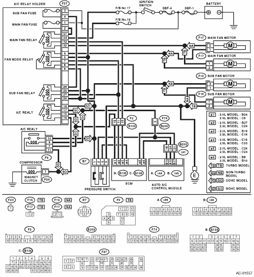
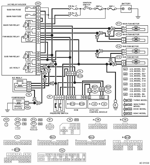
SOHC MODEL
(F27) No. 17 — (B7) No. 2:
DOHC MODEL
(F9) No. 9 — (B7) No. 2:
|
Is the resistance less than 1 Ω?
|
|
Repair the harness between the A/C relay and pressure switch.
|
4.CHECK PRESSURE SWITCH.
Measure the resistance between the pressure switch terminals.
|
Is the resistance less than 1 Ω?
|
|
Replace the pressure switch.
|
5.CHECK A/C CUT SIGNAL CIRCUIT.
1) Disconnect the connector from the auto A/C control module.
2) Measure the resistance between the auto A/C control module and the pressure switch connector.
Connector & terminal
(i48) No. 10 — (B7) No. 2:
|
Is the resistance less than 1 Ω?
|
|
Repair the harness between auto A/C control module and pressure switch.
|
6.CHECK A/C ON SIGNAL CIRCUIT.
1) Disconnect the connectors from the ECM.
2) Measure the resistance between the ECM and the auto A/C control module connector.
Connector & terminal
2.0 L model:
(B136) No. 26 — (i49) No. 17:
2.5 L model:
(B136) No. 24 — (i49) No. 17:
|
Is the resistance less than 1 Ω?
|
|
Repair the harness between the auto A/C control module and ECM.
|
7.CHECK A/C RELAY.
1) Remove the A/C relay of the main fuse box or relay holder.
2) Check the A/C relay. 
|
Does relay operate normally?
|
|
|
8.CHECK POWER SUPPLY TO MAGNET CLUTCH OF A/C COMPRESSOR.
1) Turn the ignition switch to OFF, and connect the A/C relay and all disconnected connectors.
2) Start the engine and turn the A/C switch to ON.
3) Turn the temperature control dial at maximum cool position.
4) Measure the voltage between magnet clutch harness connector and chassis ground.
Connector & terminal
(F24) No. 1 (+) — Chassis ground (−):
|
Is the voltage 10.5 V or more (at normal temperature)?
|
|
Repair the harness of the A/C compressor power supply circuit.
|
9.CHECK MAIN FAN MOTOR OPERATION.
1) Start the engine and turn the A/C switch to ON.
2) Check the operation of the main fan motor.
|
Does main fan motor operate normally?
|
|
|
10.CHECK POWER SUPPLY TO MAIN FAN MOTOR.
CAUTION:
Be careful not to overheat the engine during repair.
1) Turn the ignition switch to OFF.
2) Disconnect the connector from the main fan motor.
3) Start the engine, and warm it up until engine coolant temperature rise to 100°C (212°F) or more.
4) Stop the engine and turn the ignition switch to ON.
5) Measure the voltage between main fan motor harness connector and chassis ground.
Connector & terminal
Non-turbo model:
(F17) No. 2 (+) — Chassis ground (−):
Turbo model:
(F17) No. 1 (+) — Chassis ground (−):
|
Is the voltage 10 V or more?
|
|
Repair the harness of main fan motor power supply circuit.
|
11.CHECK MAIN FAN MOTOR GROUND CIRCUIT.
Measure the resistance between main fan motor harness connector and chassis ground.
Connector & terminal
Non-turbo model:
(F17) No. 1 — Chassis ground:
Turbo model:
(F17) No. 2 — Chassis ground:
|
Is the resistance less than 1 Ω?
|
|
Repair the harness of main fan motor ground circuit.
|
12.CHECK MAIN FAN MOTOR.
Connect the positive terminal (+) of the battery to No. 2 terminal (non-turbo model), No. 1 terminal (turbo model) of the main fan motor connector, and the negative (−) terminal to No. 1 terminal (non-turbo model), No. 2 terminal (turbo model). Check that the main fan motor rotates.
|
Is the main fan motor rotating?
|
|
Replace the main fan motor.
|
13.CHECK POOR CONTACT OF THE MAIN FAN MOTOR CONNECTOR.
Check poor contact of main fan motor harness connector.
|
Is there poor contact in the connector?
|
|
Repair the poor contact of main fan motor connector.
|
14.CHECK SUB FAN MOTOR OPERATION.
1) Start the engine and turn the A/C switch to ON.
2) Check the operation of the sub fan motor.
|
Does sub fan motor operate normally?
|
|
|
15.CHECK POWER SUPPLY TO SUB FAN MOTOR.
CAUTION:
Be careful not to overheat the engine during repair.
1) Turn the ignition switch to OFF.
2) Disconnect the connector from the sub fan motor.
3) Start the engine, and warm it up until engine coolant temperature rise to 100°C (212°F) or more.
4) Stop the engine and turn the ignition switch to ON.
5) Measure the voltage between sub fan motor harness connector and chassis ground.
Connector & terminal
Non-turbo model:
(F16) No. 2 (+) — Chassis ground (−):
Turbo model:
(F16) No. 1 (+) — Chassis ground (−):
|
Is the voltage 10 V or more?
|
|
Repair the harness of sub fan motor power supply circuit.
|
16.CHECK SUB FAN MOTOR GROUND CIRCUIT.
Measure the resistance between sub fan motor harness connector and chassis ground.
Connector & terminal
Non-turbo model:
(F16) No. 1 — Chassis ground:
Turbo model:
(F16) No. 2 — Chassis ground:
|
Is the resistance less than 1 Ω?
|
|
Repair the harness of sub fan motor ground circuit.
|
17.CHECK SUB FAN MOTOR.
Connect the positive terminal (+) of the battery to No. 2 terminal (non-turbo model), No. 1 terminal (turbo model) of the sub fan motor connector, and the negative (−) terminal to No. 1 terminal (non-turbo model), No. 2 terminal (turbo model). Check that the sub fan motor rotates.
|
Does the sub fan motor rotate?
|
|
Replace the sub fan motor.
|
18.CHECK POOR CONTACT OF THE SUB FAN MOTOR CONNECTOR.
Check poor contact of sub fan motor harness connector.
|
Is there poor contact in the connector?
|
|
Repair the poor contact of sub fan motor connector.
|
19.CHECK FOR POOR CONTACT OF THE AUTO A/C CONTROL MODULE CONNECTOR.
Check poor contact of auto A/C control module connector.
|
Is there poor contact in the connector?
|
Replace the auto A/C control module.
|
|