|
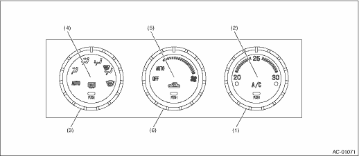
(1) |
Temperature control dial |
(3) |
Mode control dial |
(5) |
FRESH/RECIRC switch |
|
(2) |
A/C switch |
(4) |
Rear defogger switch |
(6) |
Fan speed control dial |
|
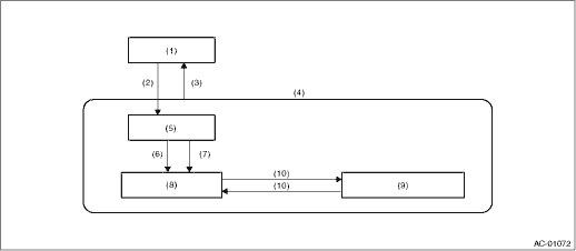
(1) |
Normal operation |
(4) |
Self-diagnosis function |
(8) |
Sensor check (Step operation) |
|
(2) |
Set the air flow control dial to the AUTO position, and the fan speed control dial to the AUTO position. Then, turn the ignition switch from OFF to ON while holding down the FRESH/RECIRC switch and the A/C switch. |
(5) |
Display check |
(9) |
Output device operation (Step operation) |
|
(3) |
Turn the fan speed control dial to the OFF position, or the ignition switch from ON to OFF. |
(6) |
After completing the display check (approximately 8 seconds) |
(10) |
Press the A/C switch. |
|
(7) |
Press the rear defogger switch. |

NOTE:
When checking the sunload sensor indoor or in the shade, an open circuit might be indicated. Always check the sunload sensor at a location exposed to direct sunlight.
|
No. |
Target for inspection |
Air flow control dial position |
|
1 |
In-vehicle sensor |
AUTO |
|
2 |
Ambient sensor |
VENT |
|
3 |
Evaporator sensor |
B/L |
|
4 |
Sunload sensor *1 |
HEAT |
|
5 |
Air mix door actuator PBR |
D/H |
|
6 |
Meter communication |
DEF |
*1: For a sunload sensor open circuit, only the current malfunction is displayed. (However, it is possible to display past failures for short circuits.)
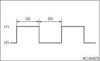
• The LED blinking pattern for open circuit failures
|
(1) |
Light ON |
|
(2) |
Light OFF |
|
(3) |
Approx. 1 sec. |
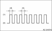
• The LED blinking pattern for short circuit failures
|
(1) |
Light ON |
|
(2) |
Light OFF |
|
(3) |
Approx. 0.2 sec. |
|
Step |
1 |
2 |
3 |
4 |
5 |
6 |
7 |
8 |
|
Fan control dial position |
AUTO |
1st |
2nd |
3rd |
4th |
5th |
6th |
7th |
|
Fan speed (%) |
24.0 |
24.0 |
34.0 |
45.0 |
42.0 |
59.0 |
71.0 |
100.0 |
|
Mode door actuator |
VENT |
VENT |
VENT |
B/L |
HEAT |
HEAT |
D/H |
DEF |
|
Intake door actuator |
FRE |
REC |
REC |
FRE |
FRE |
FRE |
FRE |
FRE |
|
Air mix door actuator |
Maximum cool (0%) |
Maximum cool (0%) |
Maximum cool (0%) |
Mid (50%) |
Mid (50%) |
Maximum hot (100%) |
Maximum hot (100%) |
Maximum hot (100%) |
|
Compressor (Magnet clutch) |
OFF |
ON |
ON |
ON |
ON |
ON |
ON |
ON |